
Techniques to Measuring Warpage and Waviness for Better Results

The metrology instruments used to measure warpage and waviness on a surface include dial gauges, surface profilers, and coordinate measuring machines (CMMs). However, because warpage and waviness is a three-dimensional characteristic, it can be difficult to accurately measure with conventional measurement methods that simply measure points and lines.
Depending on the shape or size of the part, there are many situations in which conventional methods are unable to accurately measure warpage and waviness or are physically unable to measure it at all.
Here we will explain the basics of waviness, warpage, and the various measurement methods common today. We will also touch on the problems in conventional measurement methods when it comes to waviness and the latest solutions to them.
- Waviness and Warpage
- Parallelism and Flatness
- The Importance of Warpage/Waviness Measurement and Common Problems
- Solutions to Common Warpage and Waviness Measurement Problems
- Summary: Dramatic Improvement and Higher Efficiency Warpage/Waviness Measurement
Waviness and Warpage
Waviness/warpage is a term that describes something that twists and bends. In general, waviness/warpage on a part refers to a gradually undulating shape on its surface.
Although the following figure shows an extreme example, the entire surface of the sample may be subject to a combination of twisting and bending (upward and downward) at the center or edges of the part. In cases where micron level accuracy is needed for flatness, visual judgment is impossible.
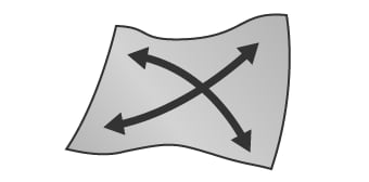
- A
- Twisting
- B
- Bending (upward and downward)
- C
- Edge warpage
The only way to evaluate warpage and waviness effectively is to measure whether or not the undulations across the entire target surface exceed the flatness and parallelism tolerances for a particular sample. Flatness and parallelism are explained in detail below. The measurement of slight undulations over the entire surface can be very complicated and leads to some difficulties. We will later introduce the methods for measuring warpage and waviness, common problems that people run into when trying to take these measurements, and solutions to these problems.
Parallelism and Flatness
Warpage/Waviness composed of complex undulations can be defined using GD&T. It is generally defined by the form tolerance of flatness or the orientation tolerance of parallelism. While similar in some regards, parallelism, unlike flatness, requires a datum (a reference plane or line).
Flatness
Flatness is defined as the deviation between a perfectly flat surface and the plane of interest. An example of a flatness call out on an engineering drawing is shown below.
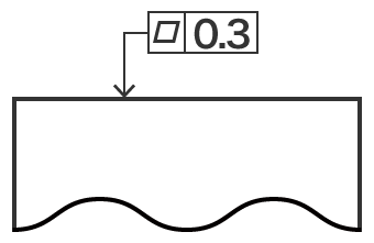
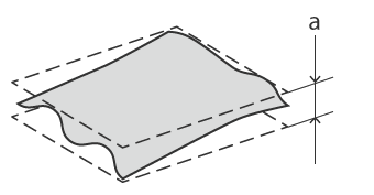
- a
- 0.3 mm (0.012") variation or less
Flatness can be calculated by projecting two perfectly flat and parallel planes above and below the surface of interest. The first projected plane can be placed at the high point of the surface of interest. The second projected plane can then be placed at the low point of the surface of interest. The perpendicular distance between the two projected planes would then be the resulting flatness measurement. Therefore, when the tolerance specifies how flat the target surface should be, the distance between the high point projected plane and the low point projected plane must be less than the flatness callout to pass the tolerance check. In this figure, the distance of 0.3 mm (0.012") or less is defined as the tolerance.
Parallelism
Parallelism is a GD&T callout which measures how parallel two lines or planes are to each other.
The major difference between flatness and parallelism is that parallelism requires a datum (a reference plane or line).
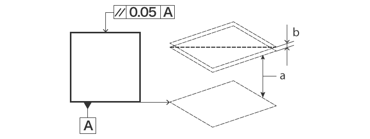
- a
- Parallel projection
- b
- 0.05 mm (0.002") variation or less
The plane indicated by the instructional arrow in the figure must be parallel to datum plane A (a plane which is defined as flat even if there is warpage/waviness on the actual target) and must fall between two projected planes separated by no more than 0.05 mm (0.002") in the direction of said instructional arrow.
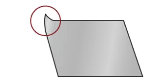
For thin targets such as sheet metal material, plastic sheets, films, PCBs, and smart-phone protective glass, variation in thickness may cause warpage/waviness and affect parallelism.
The Importance of Warpage/Waviness Measurement and Common Problems
In many cases, waviness occurs as a result of heat, residual stress, or other stress during manufacturing. The following processes and stresses are typical causes of curvature.
- Pressing (residual stress caused by punching or stamping)
- Conditions during plastic injection molding (temperature and pressure of the molten plastic and mold)
- Component mounting on PCBs (heating during the reflow process)
In sheet materials, which have uneven thickness, the storage temperature may result in warpage/waviness due to differences in the rate of thermal expansion.
This warpage/waviness is a shape defect that will impact the manufacturing process and yield rate. When warpage/waviness occurs on PCBs, it may cause contact failures such as lead lifting of the mounted electronic components. To maintain stability, it is important to correctly measure any material curvature before and after forming.
A variety of measurement methods are traditionally used to measure warpage/waviness, these include the following.
- Attaching a height gauge to an arm and reading the changing height measurements while tracing the gauge along the target surface
- Using a glass master standard with a flat surface and placing an optical flat in contact with the measurement surface in order to measure the number of resulting stripes (optical interference fringe: Newton’s rings)
- Measurement using a profile measurement system or coordinate measuring machine
Warpage/waviness measurement using these conventional contact-type measuring instruments may come with some drawbacks.
Common problems measuring warpage and waviness with profile measurement systems
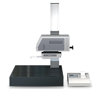
A profile measurement system measures and records the profile of a target by tracing its surface with a probe called a stylus.
In recent years, profile measurement systems have been developed that use a laser instead of a stylus to measure complex shapes by tracing the profile in a non-contact manner. Some models are even able to perform measurement of both the top and bottom surfaces.
Warpage/waviness measurement using a profile measurement system typically encounters the following challenges.
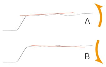
- A
- Upward slope
- B
- Downward slope
- Because the target is measured by tracing along a line, it is difficult to identify three dimensional warpage/waviness characteristics.
- It is not possible to identify the conditions of the entire target surface.
- When there are irregularities (mounted chips) on the measured surface, as there are on a PCB after components are mounted, it is difficult to detect whether or not there is warpage or waviness present on the PCB itself.
- Setting a reference plane using single lines is difficult, and as a result, measurement error may occur (see figure).
Common problems measuring warpage and waviness with coordinate measuring machines
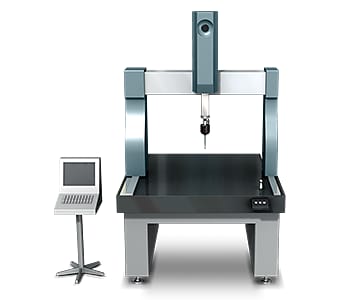
In general, when measuring warpage or waviness using a coordinate measuring machine, the probe will contact four or more corners on the measured surface of the target.
For example, in the case of a plate, generally six to eight points are collected. When the measurement area is large, warpage measurement accuracy can be improved by increasing the number of data points to collect more measurement data.
However, warpage and waviness measurements encounter the following problems.
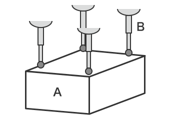
- A
- Target
- B
- Probe
- Because data points are gathered via contact, it is difficult to identify the entire shape of the target.
- Measuring more points to acquire more measurement data can be time consuming, and even with more data points, a full understanding of the target in its entirety is impossible.
Solutions to Common Warpage and Waviness Measurement Problems
Because conventional contact-type measuring instruments measure shapes using lines or points, they cannot measure the entire surface of the measurement target. Even when more points are measured to acquire more measurement data, many man-hours are required and it still might not be possible to identify warpage or waviness and other characteristics of complex shape for the entire target. In many cases, warpage or waviness measurement requires experience, knowledge, and skill that companies may not be able to provide. Securing the necessary measurement personnel is also a major problem, as is variation in the measured results between different operators.
To resolve these common measurement difficulties, KEYENCE has developed the VR Series 3D Optical Profilometer.
The VR Series accurately captures the 3D shape of an entire surface through non-contact measurement. It also measures the overall shape by 3D-scanning the target on the stage in as little as one second with high accuracy. This allows quantitative measurement and inspection to be instantaneously performed without variation in the measurement results. This section introduces some specific advantages that the VR Series can provide.
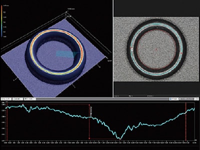
Advantage 1: Scan the 3D shape of the target surface. The shape of the entire target can be identified instantaneously.
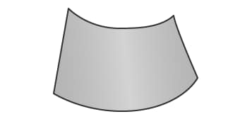
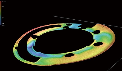
In the case of flexible parts such as O-rings, measuring and inspecting warpage, waviness, or curvature using contact-type measuring instruments can be difficult because pressure from probes or other tools change the shape of the part.
With the VR Series, you only need to place the target on the stage and scan it. The 3D shape of the target can be captured by non-contact means without the need for any fixturing. The system allows for height color maps and quick profile measurements to be taken with ease, making it possible to visualize and identify the locations and precise numerical values of shape defects. This makes it simple to identify and correct the defects caused by the molds, dies, and forming conditions. Because the shape data is measured quantitatively, it is possible to easily manage warpage and waviness based on tolerances or to use the measurements for trend analysis.

Advantage 2: Visualize warpage and waviness in a color map. Share problems using visual data.
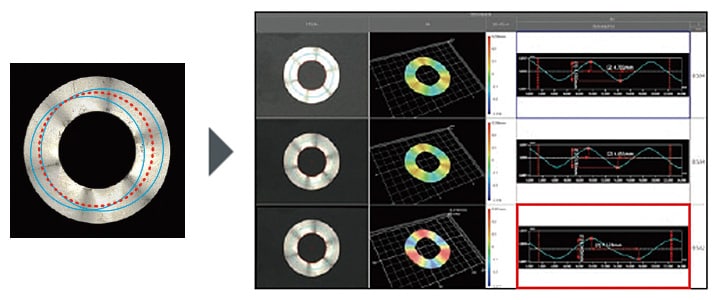
Unexpected deformation of materials can occur during pressing due to mechanical stress. Care must be taken to prevent warpage, waviness, and other shape deformations. However, with conventional contact-type measuring instruments, it can be difficult to measure warpage and waviness on an entire part, particularly for small metal parts.
Even with small and thin metal parts, the VR Series can perform a non-contact scan of the entire shape in as little as one second by simply placing the part on the stage. This makes it possible to instantly capture the warpage or waviness of the entire target and output the data in a color-coded map. By sharing data that is easy to understand and interpret visually, defect locations and potential causes can be identified, leading to quick countermeasures and the implementation of preventative maintenance.
With the VR Series, strict positioning of the target is not required. By simply placing the part on the stage, its orientation is corrected automatically, allowing for easy quantitative measurement and inspection.
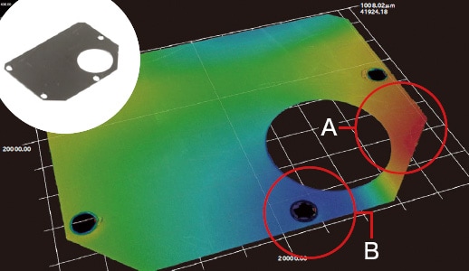
- A
- High
- B
- Low
Advantage 3: Analyze multiple sets of data at once with various data display options.
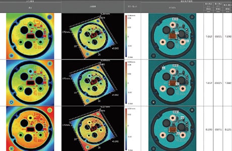
The VR Series can measure the 3D shape of an entire part by scanning the target surface in as little as one second. This makes it possible to acquire quantitative measurements on a large number of parts in a shorter time than with conventional methods. Multiple sets of efficiently collected measurement data can be displayed in lists, and the same series of measurements can be applied to all data sets at the same time.
This allows flatness to be measured on multiple parts at once and for any variation to be identified in moments. This makes it possible to easily perform quantitative analysis as to the extent of any warpage or waviness when comparing OK parts and No Good parts.
- Left
- With a conventional instrument, accurate comparison is difficult due to differences in the measurement locations and variation in the measured values.
- Right
- With the VR Series, measurement is performed instantaneously without the need for fixturing. Quantitative comparison and analysis of multiple sets of measurement results can be performed easily by displaying them side-by-side and applying the same series of measurements to all data sets at the same time.
Summary: Dramatic Improvement and Higher Efficiency Warpage/Waviness Measurement
The VR Series can instantaneously measure warpage, waviness, and other 3D deformations using high-speed and non-contact 3D scanning.
- Because the entire surface is measured, it is possible to identify all locations of warpage and waviness on the part and perform profile measurements at any desired location.
- Non-contact, high accuracy shape measurement is possible even for soft targets such as rubber and flexible plastic.
- No fixturing is required. Just place the part on the stage and press a button to complete measurement.
- 3D shapes can be analyzed in a color map. By sharing data that is easy to understand and visualize, it is simple to formulate and implement countermeasures.
- Multiple sets of measurement data can be easily and quantitatively compared and analyzed.
This allows parameters such as flatness tolerances to be configured for multiple sets of measurement data at the same time. Identification of OK/No Good products and data sharing are possible, allowing for rapid analysis and troubleshooting on bad parts. The VR Series can deliver dramatic improvements in work efficiency for measurement, defect analysis, and implementing preventative measures.
