Fluorescence Microscopes
An all-in-one fluorescence imaging microscope that captures clear images with full electronic control and no darkroom required. This system greatly improves upon the functionality of conventional fluorescence microscopes, offering live cell imaging, high-resolution observation of entire tissues, and much more.
Lineup
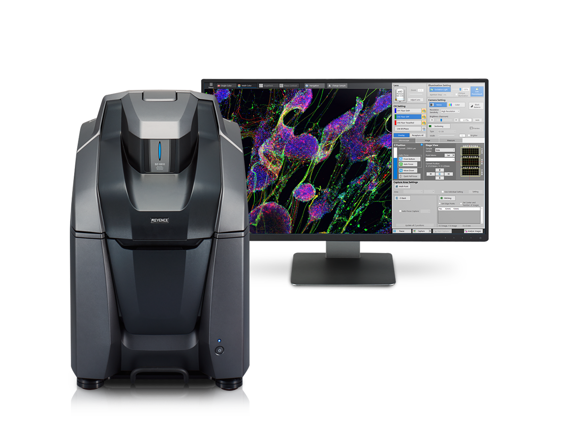
The BZ-X Series is an all-in-one fluorescence microscope equipped with advanced observation capabilities, a fully-motorized control system for instant target acquisition, and advanced imaging and analysis functions. With a built-in darkroom and an installation area of ~ 1' x 2' the BZ-X inverted fluorescence microscope can be set up in any location for optimal testing efficiency. The high-sensitivity, cooled CCD camera can be switched between monochrome and color imaging, and supports fluorescence, brightfield, and phase contrast imaging. The large motorized stage can quickly move to the desired observation location, while high-speed auto-focusing and automatic capture conditions allow any user to easily capture publication-quality images. Additionally, the BZ-X Series all-in-one microscope is capable of three-dimensional analysis, motion analysis, and time-series quantification.
A fluorescence microscope is an optical microscope that uses fluorescence to observe samples. Fluorescence microscopy illuminates a target with a specific wavelength of light, which causes the target to absorb the light and emit a longer wavelength. This causes the target to glow within an otherwise dark field of view.
Unlike conventional microscopes, fluorescence microscopes use a highly sensitive detector to measure only the emitted light from the target, enabling high-resolution observation and imaging.
Benefits of Fluorescence Microscopes
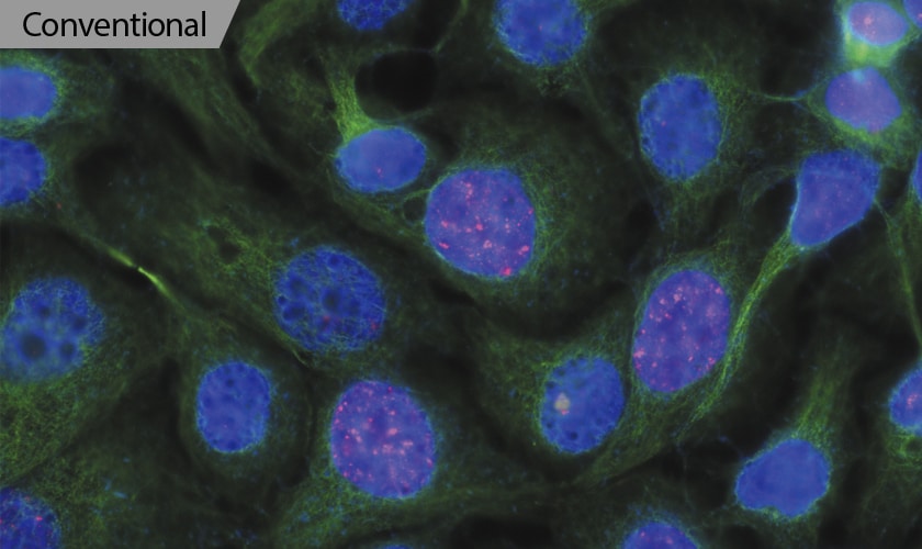
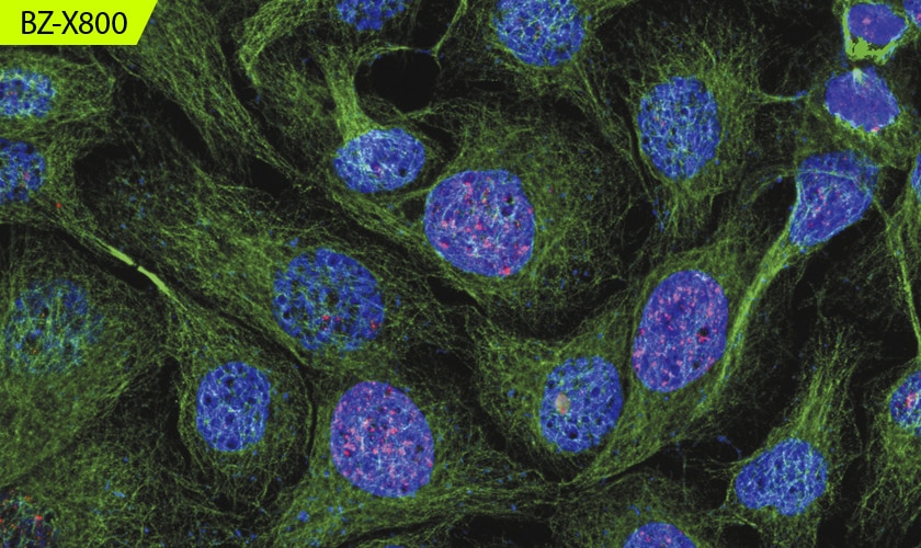
Fluorescence microscopes emit light onto cells that have been stained with a fluorescent dye, making it possible to see the cell characteristics more clearly than with a conventional microscope that uses reflected light. Fluorescence microscopes are also highly sensitive and can detect differences in brightness and wavelength. This enables observation of details that cannot be seen with standard white-light optical microscopes.
The resolution of an optical microscope varies according to the wavelength of light used for observation and is limited by the aperture of the objective lens. The observation resolution is also limited by the shortest wavelength of visible light with the objective lens, which is about 200 nm.
With a fluorescence microscope, however, cells are stained with a fluorescent dye for observation at higher resolutions with greater contrast between structures in the cell. Observation images for multiple fluorescent dyes can also be obtained by using different dyes and bandpass filters for the various spectrums.
Most confocal laser microscopes have a narrow wavelength range that can be excited at a given time. If the pinhole diameter is reduced to increase the resolution, higher laser power is required for the smaller diameter. This can cause fading of the fluorescent dye and damage to living cells. Conversely, fluorescence microscopes can excite a wide range of cells by combining a white light source and an excitation filter. Using a high-sensitivity image receiving element allows for fluorescence observation with minimal damage to samples, making it easier to observe living cells.
Most confocal laser microscopes achieve high resolution by using a single-wavelength laser and a small pinhole diameter to minimize the excitation region. However, if the excitation wavelength is narrowed and the pinhole diameter is reduced, the light intensity decreases and noise increases. Increasing the laser power and reducing the scanning speed solves this problem, but this increases the risk of damage to living cells.
Modern fluorescence microscopes use a white light source with wavelengths ranging from ultraviolet to near-infrared, and using an appropriate excitation filter for the fluorescent reagent enables loss-free imaging of excited fluorescence. The high-sensitivity image receiving element allows for a weaker light intensity to be used and reduces the risk of damage to samples. This enables easy time-lapse and live imaging for high-definition observation of living cells.
Modern fluorescence microscopes use an electronic projection element for structured illumination that enables high-speed scanning of specimens. The BZ-X Series is equipped with an optical sectioning module that uses a white light source instead of lasers, minimizing damage. This allows for high-accuracy optical sectioning imaging in a wide range of wavelengths with no fluorescence blurring.
With thick specimens, clear images cannot be easily captured with conventional fluorescence imaging because of fluorescence blurring. Fluorescence blurring is caused by out-of-focus scattered light in the Z-direction that is mixed with clear signals from focused surfaces.
In modern fluorescence microscopes, the excitation light is structured into stripes and projected onto the specimen. Although the stripes are clearly projected on focused surfaces, they are not clearly projected on out-of-focus surfaces and cannot be observed, reducing noise. Multiple images are then automatically obtained by scanning the specimen while moving the pattern. The pattern movement allows for areas with fluorescence blurring to be accurately separated from the rest of the sample. This process enables capturing of clear sectioned images that show only signals from focused surfaces.
There are two methods for structuring the excitation light: using a physical grid or using an electronic projection element. In addition to automatically optimizing the pattern width according to the magnification, using an electronic projection element makes it possible to convert the pattern to a pinhole shape for imaging at a higher resolution.
Fluorescence Microscope Case Studies
Cancer research, cellular biology: Localized observation of exosomes
Exosomes have diameters of 30 to 150 nm, so they are difficult to observe with optical microscopes. Electron microscopes are not commonly used for measuring physical properties because the electron beam alters the cells. The equipment is also large, so the number of facilities with an electron microscope is limited.
For exosome observation with the BZ-X Series, using a fluorescent dye enables visualization of the exosomes, and observation of the RNA contained in the extracted exosome (the RNA cargo) and the exosome membrane is possible. This observation allows for monitoring of time-dependent exosome localization changes and exosomes being taken into cells (a process of intercellular communication via exosomes).
The BZ-X Series is receiving attention as a new piece of technology that enables analysis of exosomes with higher accuracy.
Clinical medicine: Automatic analysis of CD68 (macrophage) glomerulus occupancy rate
CD68 (macrophage) permeation into the kidney glomerulus is a universal phenomenon seen in all progressive kidney diseases. CD68 observation involves HE staining followed by capturing a bird’s-eye view of a kidney biopsy. Focusing on a thick sample can be difficult with a normal microscope, however the BZ-X Series z-stack image capturing enables observation with the entire image in focus. Additionally, high-speed image stitching enables capturing a large image with high resolution for analysis. Glomeruli—microscopic balls made of capillaries—govern the filtration function of the kidney, with approximately 1 million glomeruli in a single kidney. Permeation of CD68 into these glomeruli leads to the phenomenon of fibrosis of kidney tissue and progressive kidney disease. The BZ-X Series offers significant advances in treating this disease, making it a popular observation system.
Materials chemistry: Visualization of fiber dispersion in composites
Composites made of mixed organic and inorganic materials may not have the intended characteristics if they are not evenly blended during the manufacturing process. Organic and inorganic material mixing can generally be confirmed using an optical microscope or an electron microscope. However, if the organic and inorganic materials are the same color, visualizing the dispersion of only the organic material may be difficult. In general, organic materials shine but inorganic materials do not. Fluorescence observation utilizes that characteristic to enable visualization of only the organic materials.
The BZ-X Series captures continuous fluorescence and optical (brightfield) images instantaneously and easily produces overlay images. This provides a clear understanding of the dispersion of the organic material while looking at the entire shape. The shining parts can be converted to a binary image using quantitative analysis software. This conversion further allows for quantitative evaluation based on substance count, area, and other numeric parameters. The BZ-X Series can provide images with a wide field of view regardless of magnification, thereby enabling accurate evaluation and judgment.
Quantitative analysis with well plates
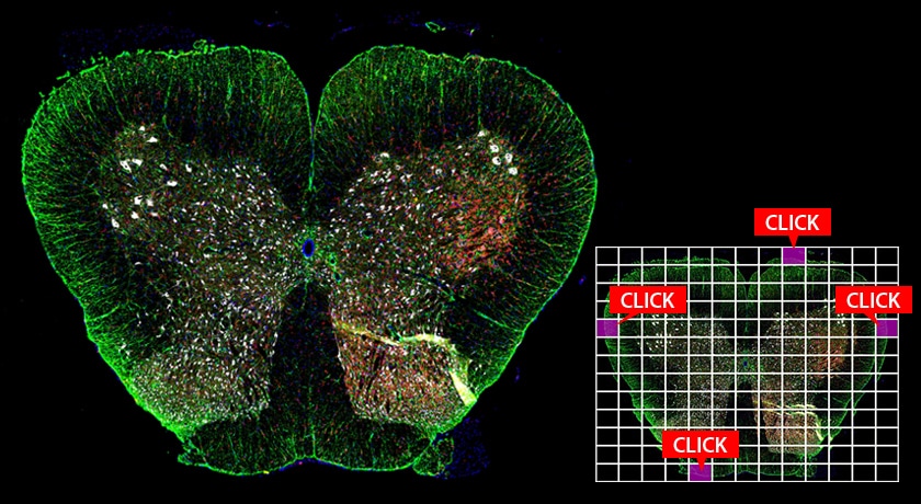
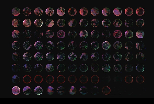
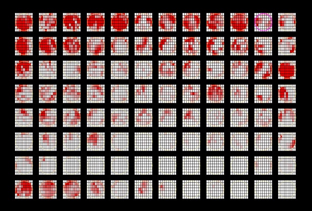
The large motorized stage ensures support for a wide variety of targets. Paired with advanced navigation functions for quickly finding the desired area, the stage enables researchers to perform fast wide-area observations in which they never lose sight of their target. Capture conditions for a user-specified point can also be instantly applied to all fields of view within wells. This allows all wells to be imaged using the same capture conditions.
Uniform capture conditions enable high-reproducibility, and all settings can be easily configured, eliminating the need for users to monitor the microscope from start to finish.
As well as reducing measurement time and enabling accurate analysis with no variations in conditions, the high-density measurement data utilizing high-definition images from the all-in-one fluorescence microscope provides unprecedented clear observation.
Capturing changes in living cells and tissues
With the BZ-X, it is possible to capture extended time-lapse images of brightfield, fluorescence, and phase-contrast images at specified intervals. By default, time-lapse observations require a large time investment and the likelihood for failed observation increases, primarily due to cell damage, cells drifting out of focus, and cells leaving the field-of-view.
The BZ-X is equipped with various functions to combat common problems encountered when performing time-lapse imaging. Because the BZ-X Series uses white light instead of a laser, cell damage is minimized, even over long periods of time. Additionally, the BZ-X has advanced imaging functions that reduce the amount of exposure time of the sample. The BZ-X is also equipped with tracking functions to ensure the cells remain in focus and within the field-of-view, even if the specimen changes location or shape. Due to advanced tracking and imaging algorithms, the BZ-X microscope is the ideal solution for performing time-lapse imaging.
Versatility for a wide-range of applications
The cooled CCD monochrome camera provides clear confocal-like images that combine high sensitivity and low noise.
This enables clear fluorescence imaging even with low excitation light, minimizing both photobleaching and damage to cells sensitive to phototoxicity. The camera is also able to image dyes such as Cy7 in the near-infrared range, allowing for observation of cells located in deep tissue layers. Additionally, it uses a metal halide lamp as the fluorescence light source for its broad wavelength range from UV through to IR. This enables support for a range of fluorescence pigments simply by changing filters. The unique optical sectioning technology in the BZ-X Series uses an electronic projection element for structured illumination to provide impressively clear images. Single-click capture of high-definition images is possible with no fluorescence blurring.
Clear images can be captured even from thick specimens through accurate detection of confocal point information. This feature enables capturing of various specimens such as animal cells, plant cells, and cultured tissues as they are. Optical sectioning also provides high-accuracy, cross-sectional images without fluorescence blurring from other focal planes. Clear Z-stacks can then be transformed into realistic 3D renderings, allowing for accurate localization analysis.
Frequently Asked Questions About Fluorescence Microscopes
Although both devices use fluorescence emitted by fluorescent proteins or the specimen itself for observation, a fluorescence microscope uses a white light source while a confocal microscope uses a laser. Other major differences between these two types of microscopes are listed below.
Fluorescence microscopes:
• Light sources include mercury lamps (ultra-high-pressure mercury lamps, metal halide lamps, etc.) and LEDs.
• Light is projected onto the entire surface of the target, and an image receiving element is used to capture the excited fluorescence.
• Light from beyond the focal plane is also captured. Modern fluorescence microscopes use structured illumination to eliminate blurring.
• The white light source offers a wide range of wavelengths, from ultraviolet to near-infrared, for capturing fluorescence of various wavelengths with a single light source (use of appropriate filters is required).
Confocal microscopes:
• A laser is used as the light source.
• The laser is irradiated in the shape of a dot and scanned across the target surface, and the excited fluorescence is received using a photomultiplier to create the observation image.
• Blurring from beyond the focal plane can be eliminated by placing a pinhole at a position conjugate to the focal plane, ensuring only the focal plane is captured.
• Generally, single-wavelength excitation light is emitted from a single laser tube. Additional laser tubes are required for detecting multiple fluorescences.
Fluorescence microscopes are primarily used for observing, imaging, and analyzing biological samples, such as tissue and cells. They are commonly used in the research and study of cancer, cellular biology, pharmaceuticals, and clinical medicine.
The BZ-X Series has a built-in darkroom and an installation size of ~ 1' x 2', so high-contrast fluorescence imaging is possible anywhere.
Despite the compact size, the BZ-X Series includes a large motorized stage that can be used with well plates for efficient observation of multiple samples. Up to six objective lenses can be mounted, and the CCD camera can switch between color and monochrome modes. Nearly all operations can be performed on a PC, from switching objective lenses and filters to adjusting focus. Low photobleach mode and a high-speed auto-focus function allow anyone, even beginners, to capture clear images.
The system also offers a wide range of extended functions to support a variety of specimens, including optical sectioning, automatic image stitching, and cytometry. The BZ-X Series is a versatile microscope, able to be used for a wide-variety of applications.
Fluorescent light microscopes consist of a camera (CCD, CMOS, etc.) that serves as the detector, a filter, a light source, and a beam splitter. The filter is composed of an excitation filter and an emission filter. In a conventional fluorescence microscope, the transmission method involves a darkfield condenser that completely cuts off the excitation light irradiating the sample from the optical observation path. In recent years, however, the development of dichroic mirrors that reflect short wavelengths and transmit long wavelengths, and objective lenses made of glass with low autofluorescence, has led to the mainstream use of the epi-illumination method. The following section explains the components of epifluorescence microscopes.
CCD camera (detector)
A CCD camera is used to detect the emitted light for fluorescence observation. The camera is connected to a computer to display the captured image.
Light source
Mercury or xenon lamps or LEDs are used as the light source.
Excitation filter
The excitation filter allows only specific wavelengths to pass through while blocking out all other wavelengths of light.
Dichroic mirror (beam splitter)
The dichroic mirror separates the excitation light from the emission light. Unlike ordinary mirrors, this mirror reflects only light at specific wavelengths and filters out all other light. As the excitation light is reflected from the sample, only the fluorescence emitted by the sample is transmitted to the CCD camera.
Emission filter
The emission filter blocks all wavelengths of light except that of the light emitted by the sample. In this way, the fluorescence emitted by the sample is filtered from all other light, including scattered light.
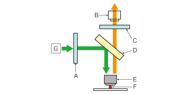
A: Excitation filter, B: CCD camera (detector), C: Emission filter, D: Dichroic mirror (beam splitter), E: Objective lens, F: Sample, G: Light source
Fluorescence Microscope Filters
Roles of filters
The excitation filter, dichroic mirror, and emission filter are housed in a single mirror unit, or “cube,” in the microscope. This mirror unit is designed to match the spectrum* of a particular fluorescent material. Some mirror units, however, do not include a filter. In such microscopes, the filter is placed on a turret. This turret is used to combine the excitation and emission wavelengths to an optimal condition.
* Spectrum: An array of light intensity distributions at different wavelengths created by light resolved by a spectrometer.
Choosing a filter
Filter selection depends on whether observation involves one or more fluorescent dyes. For example, for observation of only one fluorescent dye, select an appropriate excitation filter and emission filter for that dye. For observation of two or more fluorescent dyes, the excitation and emission filter combination will vary depending on the specific dyes. This is due to the specific spectrum of light changing between particular fluorescent dyes, so knowing the spectrum for the fluorescent dye is essential for selecting a filter.
Determining the spectrum
When selecting a filter, it is necessary to first determine both the excitation and emission spectra for each fluorescent dye. When using two fluorescent dyes, a dye separation filter with a narrow transmission range should be used for one of the dyes to eliminate the excitation of the other dye. Otherwise, if the transmission range of one filter includes the long-wavelength region, the fluorescence of the other filter will also be observed.
The filter for the other fluorescent dye should also match the desired spectrum to enable observation. Adopting filters with a narrow transmission range suitable for each fluorescent dye thus makes it possible to observe only the target signal.
Choosing an excitation filter
Broadband and narrowband filters are available, depending on the breadth of the light wavelength range. The selected filter should be as specific as possible to the excitation wavelength of the fluorescent substance. Particularly when using a mercury lamp light source, efficient excitation requires the emission lines of the mercury lamp to be incorporated into the excitation wavelength. In general, using a strong light in a different wavelength band than the excitation wavelength of the fluorescent material being observed increases the background light for a brighter image. However, because this can damage the sample unnecessarily, a narrow-band filter is generally preferred.
Choosing an emission filter
The choice of emission filter will depend on the light source. When using a white light source, extraction of only the wavelengths necessary for excitation is required because of the wide light band, so optical filters are generally used.
Optical filters come in a variety of types, from simple colored glass filters to interference filters designed to transmit only light at certain wavelengths. To extract only light at a certain wavelength, a bypass filter that transmits only a narrow range of wavelengths is generally used. For observation of only one fluorescent dye, either a long-pass filter or a short-pass filter is used.
Long-pass and short-pass filters
Long-pass and short-pass filters are used when observing a single fluorescent dye. Long-pass filters reduce background noise by blocking the excitation light and allowing all other light to pass through.
Short-pass filters, however, only allow wavelengths shorter than a certain wavelength to pass through. These filters are often used for observation of a single dye because they maximize signal detection.
Bandpass filters
Bandpass filters are used when more than one fluorescent dye is used in a sample. The light from each dye is separated, so the detector receives only the fluorescence emitted by the sample.
Summary
The fluorescence mirror unit can be assembled individually by purchasing the filters and dichroic mirror as necessary to match the light source. This allows users to create the ideal combination of mirror units for the specific fluorescent dye being used.
Considering the above, reliable fluorescence imaging requires proper selection of filters. With an all-in-one fluorescence microscope, the filter cubes, light source, and lenses are integrated and easily adjusted for effortless installation, simplified operation, and reliable observation even for those not familiar with operating a microscope.
Our unwavering commitment to providing cutting-edge technology and exceptional service makes us the leaders in sensors, measuring systems, laser markers, microscopes, and machine vision systems for manufacturers worldwide. If you're interested in this equipment, browse our catalog and get in touch with us today.
KEYENCE’s Fluorescence Microscope Applications and Methods website includes information for any researcher that uses microscopes. This website is a rich source of application examples, information on analysis methods, and BZ-X Series testimonials from researchers in various fields.