
Heavy Duty Type Digital Pressure Sensors
GP-M series
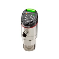
Main Unit, Built-in temperature sensor Compound-pressure Type, ±100 kPa GP-M001T

Specifications
Model | GP-M001T | |||
Rated pressure | –14.50 to +14.50 PSI | |||
Possible display range | –17.40 to +17.40 PSI | |||
Allowable pressure | 58 PSI (400 kPa) | |||
Zero-cut pressure value | ±0.5% of F.S. | |||
Burst pressure | 218 PSI (1.5 MPa) | |||
Display resolution | 0.015 PSI (0.1 kPa) | |||
Fluid type | Gas or liquid that will not corrode the fluid contact part | |||
Type of pressure | Gauge pressure | |||
Precision | ±1.0% of F.S. or less*1 | |||
Repeatability | ±0.3% of F.S. or less*2 | |||
Temperature characteristics | ±0.6% of F.S. / 10°C 50°F | |||
Connection port | G3/4 (Changes to R1/8 male, R1/4 male, R3/8 male, G1/4 female, NPT1/8 male, and NPT1/4 male with available adapters.) | |||
Box rotation angle | Maximum 330° | |||
Medium temperature | –20 to +100°C –4 to +212°F (no freezing/condensation)*3*4 | |||
Power voltage | 10 to 30 VDC, Ripple (P-P): 10% max., Class 2 or LPS | |||
Current consumption | 60 mA or less (when 24 V: 30 mA or less; when 12 V: 50 mA or less. Excluding output)*5 | |||
Possible display range (temperature) | –32 to +112°C –25.6 to +233.6°F | |||
Display method | 4 column digital LED white/Vertical inversion of display is possible | |||
Display resolution (temperature) | 0.1°C 32.18°F | |||
Liquid contact temperature measurement accuracy | ±3.5°C ±6.3°F (at an ambient temperature of 25°C 77°F)*6 | |||
Display method | Status indicator (orange, green, red, blue), output indicator 1 (orange), output indicator 2 (orange), temperature indicator (white), communication indicator (green) | |||
Pressure hysteresis | During hysteresis mode: variable (Hysteresis is the difference between the upper setting value and the lower setting value) | |||
Pressure responsiveness | Control output | Selectable from 3 to 5000 ms | ||
Analog output | As above +2 ms (90% response) | |||
Output | Output 1 control output | NPN/PNP open collector (Selectable) 30 V or less, | ||
Output 2 | Control output | |||
Analog output | Pressure analog output/temperature analog output (selectable), 4–20 mA; maximum load resistance 260 Ω | |||
Network compatibility | IO-Link*7 | |||
Environmental resistance | Enclosure rating | IP67 | ||
Ambient temperature | –20 to +80°C –4 to +176°F (no freezing or condensation)*8 | |||
Relative humidity | 35 to 85% RH (no condensation)*8 | |||
Vibration resistance | IEC60068-2-6 20 G (10 to 2000 Hz In each direction of X, Y, Z for 2 hours) | |||
Shock resistance | IEC60068-2-27 50 G (11 ms In each direction X, Y, Z 3 times) | |||
Material | Wetted part | Pressure port: SUSXM7/Diaphragm pressure port: Al2O3/O-Ring: FKM | ||
Other parts | Housing metal portion: SUS304, SUS303; Housing plastic portion: PPSU; Air hole*9: PTFE, nickel-plated brass. | |||
Applicable cable | M12 connector 4 pin | |||
Weight | Approx. 150 g 5.29 oz | |||
*1 This is the value when considering linearity + hysteresis + repeatability in a stable environment of 23°C 73.4°F. | ||||