
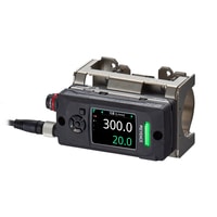
Clamp-On Flow Sensor
FD-H series
Flow Sensors Standard model 25A/32A FD-H32

Specifications
Model | FD-H32 | |||
Type | Standard model | |||
Supported pipe diameter | 1" (25A), ø28–37 ø1.10"-1.46" | |||
Supported pipe materials | Metal piping, hard plastic piping*1 | |||
Supported fluids | All fluids (water, oil, chemicals, etc.)*1 | |||
Supported fluid temperature | 0–85°C 32–185°F (no freezing on pipe surface)*2 | |||
Maximum rated flow | 1" (25A) : 200 L/min 52.8 gal/min | |||
Zero cut flow rate | 1.0 L/min 0.3 gal/min (variable, initial value) | |||
Detection principle | Delta TOF + Pulse Doppler | |||
Function for automatic correction for speed of sound in liquid | Yes | |||
Display | QVGA 2.0 model: color LCD, status indicator light | |||
Display update cycle | Approx. 10 times/second | |||
Display resolution | Instantaneous flow | 0.01/0.1/1 (L/min) (default value: 1) | ||
Integrated flow | 0.01/0.1/1 (L) (default value: 1; up to 8 digits) | |||
Response time | 0.5 s / 1.0 s / 2.5 s / 5.0 s / 10.0 s / 30.0 s / 60.0 s / 120.0 s / 200.0 s | |||
Measurement accuracy | Between 10 and 100% of F.S.: ±3.0% of RD*3*4 | |||
Repeatability | 0.5 s: ±1.0%, 1 s: ±0.7%, 2.5 s: ±0.45%, 5 s: ±0.3%, 10 s: ±0.2%, 30 s: ±0.15%, 60 s: ±0.1% of F.S.*3*5 | |||
Hysteresis | Variable | |||
Flow units | L/min m3/h G/min | |||
Pulse output increments (L) | 0.02–999.99 | |||
Pipe temperature measurement accuracy | ±2.0°C ±3.5°F (pipe temperature 0–50°C 32–122°F) , ±3.0°C ±5.4°F (pipe temperature 50–85°C 122–185°F) (ambient temperature of 25°C 77°F)*3 | |||
Network support | IO-Link*6 | |||
Heat calculation function | Unit | MJ/h kW kBTU/h*7 | ||
Display resolution | Instantaneous value (MJ/h): 0.01/0.1/1 (default value 0.1); Integrated value (MJ): 0.01/0.1/1 (default value 0.1)*7 | |||
Pulse output increments (MJ) | 0.02–999.99*7 | |||
Data accumulation | Accumulation period | Approx. 1 year | ||
Data reading | USB2.0 | |||
Power I/O connector | M12 8-pin connector (male) | |||
I/O (switchable) | Output (Ch1/2/3/4) | Instantaneous flow mode / area mode / pulse output mode / integrated flow mode / bubble detection mode / error output | ||
Analog output (Ch1/2) | 4–20 mA/0–20 mA (switchable), load resistance 500 Ω or less | |||
External input (Ch2/3) | Integrated reset input / flow-rate zero input / zero-point adjustment input / bank input | |||
Power supply | Power voltage | 20–30 VDC, ripple (P-P) 10% included, Class 2/LPS | ||
Current consumption | 240 mA or less (when using flow sensor standalone; with analog output; excluding load current)*8 | |||
Protection circuit | Protection against reverse power connection, power supply surges, output short circuits, and output surges | |||
Environmental resistance | Enclosure rating | IP65/67 (IEC 60529)*9 | ||
Ambient temperature | Sensor head: −20 to +60°C –4 to +140°F (no freezing); Display unit: −20 to +50°C –4 to +122°F (no freezing)*2 | |||
Relative humidity | 35–85% RH (no condensation) | |||
Vibration resistance | 10–500 Hz; Power spectral density: 0.816 G2/Hz; X, Y and Z directions | |||
Shock resistance | 100 m/s2 (approx. 10 G), 16 ms pulses, 1000 times each for X, Y and Z axes | |||
Material | Display unit | Body: PPS/PET/POM; Display window: PAR | ||
Sensor head | Body: PPS/PET/PAR/SUS304 | |||
Weight | approx. 620 g 21.87 oz | |||
*1 For fluids through which ultrasonic waves propagate, and which do not contain a large quantity of bubbles. Detection may be unstable depending on the type and condition of the pipe. | ||||