Finding The Right Solution for Height/Step Measurement
When looking for the best way to measure height or step height, there are a number of important factors to consider, including the shape of the target, the type of measurement system, and the installation environment. Selecting equipment that doesn't adequately meet your needs can lead to insufficient precision and increased man-hours during production, so choosing the right equipment is important. This site is designed to help you discover the best way to perform this measurement with confidence.
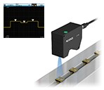
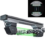
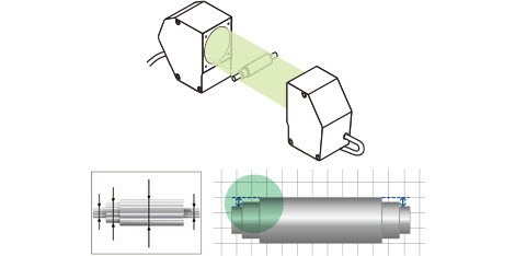
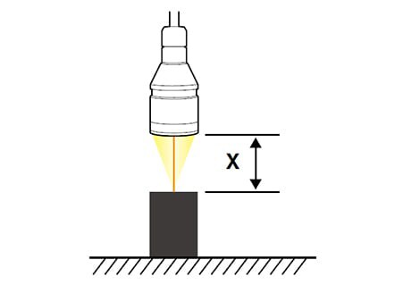
The silhouette of the target is projected, and the step height between two specified features is calculated.
KEY POINTS
Even if the shaft is tilted, step can be measured accurately when the alignment adjustment feature is utilized. Measurements are not affected by the color of the target surface.
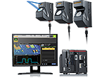
2D Telecentric Optical Method. Simultaneous measurement of up to 100 with calibrated high-speed measurement.
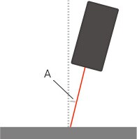
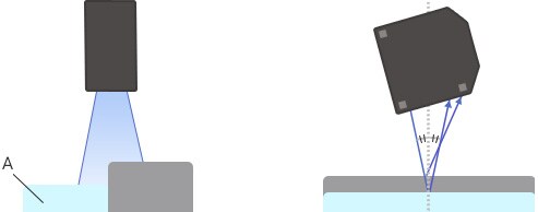
If the optical axis is not perpendicular to the target, a measurement error caused by angle θ occurs in the height value, as shown in figure 1. If θ is greater than 0.8°, the measurement error is approximately 0.01%, so correct the tilt in advance if you are concerned about its effect. You can easily correct the tilt by preparing one master workpiece and using the scaling settings.
[Figure 1]A: Optical-axis tilt θ
Transparent objects and objects with mirror finished surfaces
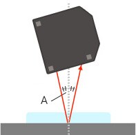
If the target is a transparent object or an object with a mirror finished surface, you have to install the sensor head tilted at an angle that is half the angle of the projected and received light, α, in relation to the target, as shown in figure 2. (When using the triangulation method.)
Also, if the target is a transparent object, a key point for stable measurement is to have the transparent object be at least as thick as a certain value. If the object is thin, the value measured for the front surface height may be lower than it should be due to the effect of the light reflected from the back surface of the transparent object. The minimum thickness limits that ensure stable measurement vary depending on the sensor head type, the transparency of the target and the reflectivity of the back surface.
[Figure 2]A: α/2
Precautions during Step Measurement
The Effect of the tilt of the sensor head
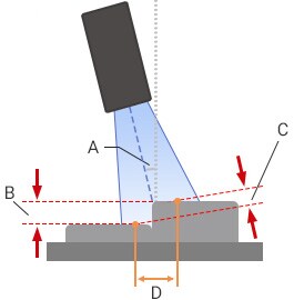
If the optical axis of the 2D laser displacement sensor is not perpendicular to the target, a measurement error caused by angle θ occurs in the step value, as shown in figure 3. The larger the distance (X) between the two points being measured for the step, the greater the measurement error. For example, even if the tilt θ is only 0.1°, the measurement error becomes approximately 50 μm if X = 30 mm. Therefore, the tilt correction function is generally used when performing step measurements.
[Figure 3]A: Optical-axis tilt θB: True stepC: Measured value D: Distance between two points (X)
Transparent objects and objects with mirror finished surfaces
If at least one of the surfaces being measured in the step measurement is a transparent object or an object with a mirror finished surface, install the sensor head tilted at an angle that is half the angle of the projected and received light, α, in relation to the target, as shown in figure 4. It is also necessary to prepare a head that is dedicated for use with transparent objects and objects with mirror finished surfaces.
Furthermore, if the target is a transparent object, it must be at least as thick as a certain value in order for the surface height to be measured accurately. If the object is thin, the value measured for the front surface height may be lower than it should be due to the effect of the light reflected from the back surface of the transparent object. The minimum thickness limits that ensure stable measurement vary depending on the sensor head type, the transparency of the target and the reflectivity of the back surface.
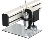
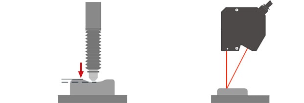
When the probe comes into contact with a soft target, the target can be compressed, which leads to a corresponding measurement error. With non-contact measurement, it is possible to measure targets that deform such as soft targets and liquid surfaces.
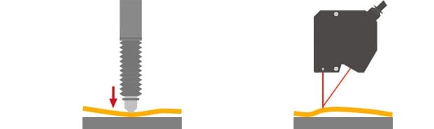
Measuring light targets
For targets that are thin and light, it is necessary to hold down the target to ensure that it does not float on an air gap in order to accurately measure the surface height. With contact measurement, the probe presses down on the target surface, which eliminates errors caused by the target floating in the air. For this reason, the contact method is better suited to this type of measurement than the non-contact method.
Measuring indentations
With a non-contact laser displacement sensor, the measurement spot (which ranges from a few micrometers to hundreds of micrometers in size) is generally smaller than the probes used in contact measurement. This makes it possible to accurately measure the base height of more narrow indentations with the non-contact method.