
High-accuracy Measurement of Free-form Surfaces on Cut Products
Parts with free-form surfaces such as impellers and propellers are machined using multi-axis machining centers that require advanced mechanical control. Many of these parts are thin, making them susceptible to deformation during machining. Because this deformation directly affects the performance of the equipment where these parts are installed, strict dimension measurement is essential.
This page explains basic knowledge of free-form surfaces, the machine tools used for machining of free-form surfaces, and types of deformation that occur during machining. It also introduces problems in conventional measurement methods as well as inspection and analysis solutions to prevent the occurrence of defective products.
- Free-form Surfaces
- Five-axis Machine Tools
- Types of Deformation Caused by Machining and Countermeasures to Them
- Problems in Conventional Measurement of Free-form Surfaces
- Solution to Problems in Measurement of Free-form Surfaces
- Summary
Free-form Surfaces
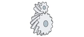
A free-form surface is a curved surface that cannot be expressed with simple formulas used for shapes such as spheres, cubes, cylinders, and cylindrical tubes. A free-form surface is expressed by setting multiple intersections and curvatures in space, supplementing the intersections using high-order equations. Parts which have free-form surfaces include impellers, which are used in products such as pumps and superchargers, and aircraft propellers. Gears such as helical gears and spiral gears may also have teeth that are composed of free-form surfaces.
When machining parts that have free-form surfaces, complex NC programs are required due to the need for multi-dimensional control. General-purpose machining centers cannot deliver the required level of accuracy, making it necessary to use high-precision five-axis machine tools.

Five-axis Machine Tools
A five-axis machine tool is a machining center that has two rotating and tilting axes in addition to three linear axes that move in the X, Y, and Z directions. Unlike three-axis machine tools, a five-axis machine tool requires no special tools or jigs. This reduces machining costs, man-hours, and the amount of setup changes while also improving machining quality and accuracy. In addition, the five-axis machine tool can perform machining with a high degree of freedom.
This section explains the differences between a three-axis machine tool and five-axis machine tool, the structure and machining principle of simultaneous five-axis machine tools, and important points regarding the introduction and operation of a simultaneous five-axis machine tool.
Differences between a three-axis machine tool and five-axis machine tool
The inside of a conventional three-axis machine tool consists of a table for fastening the workpiece and the spindle. The spindle moves left and right (X axis), forward and back (Y axis), and up and down (Z axis) relative to the workpiece in order to machine it.
On the other hand, a five-axis machine tool has two rotating and tilting axes in addition to the X, Y, and Z axes. The table where the workpiece is installed rotates. The two rotating and tilting axes consist of the A axis, which rotates the workpiece around the X axis, and the C axis, which rotates the workpiece around the Z axis. With this structure, a five-axis machine tool can machine all surfaces of the workpiece on the table except for the bottom surface, without the need to remove the installed workpiece from the table.
Therefore, a five-axis machine tool can reduce the work required for changing the workpiece installation angle and can machine complex shapes like free-form surfaces without using special tools. The ability to freely move the workpiece also minimizes tool overhang, preventing problems such as reduction in machining accuracy caused by deformation of the endmill or other tool under machining pressure.
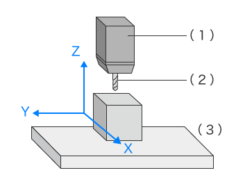
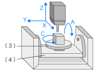
- (1) Spindle
- (2) End mill
- (3) Table
- (4) Cradle
Simultaneous five-axis machine tool
A simultaneous five-axis machine tool performs machining while operating all spindle and rotating axes. Typical five-axis machine tools perform processing by turning the A and C axes to the specified angles and cutting the workpiece, then changing the angles and cutting again. The A and C axes stop rotating while the spindle is moving. This is called indexing five-axis machining.
On the other hand, a simultaneous five-axis machine tool performs machining while moving all five axes at the same time, enabling machining of smooth free-form surfaces. Some parts such as impeller blades, bladed disks, and the inlet and outlet ports of reciprocating engines can only be machined using simultaneous five-axis machine tools.
Important points concerning five-axis machine tools
Five-axis machine tools are superior to conventional three-axis machine tools in various aspect; however, caution regarding the following points is necessary when introducing and operating such a tool.
- Introduction cost:
- With higher performance and more functions, five-axis machine tools are more expensive than three-axis machine tools. Because they require 3D CAD/CAM and NC programs, the high costs of introducing these elements can also be considered a disadvantage.
- Machining accuracy:
- When the accuracy of the axis movement is the same as that of a three-axis machine tool, the machining accuracy will be lower due to the larger number of axes. As five-axis machine tools have complex mechanisms with many moving parts, machining accuracy may also decrease if these parts lack sufficient rigidity.
- Man-hours required for setup change:
- Once set up, a five-axis machine tool can perform machining at high speeds with high accuracy. However, preparation before machining a new workpiece involves development of an NC program, setup of each axis, and other work that requires large numbers of man-hours.
Types of Deformation Caused by Machining and Countermeasures to Them
When machining, thin or fine workpieces may undergo warpage, strain, and other deformation that can result in machining error even when using tools with specified accuracy. In such cases, it is necessary to change the design to prevent deformation or consider the resulting deformation in advance when machining the workpieces. This section introduces the causes of deformation during machining.
Deformation caused by external forces such as clamping force and machining pressure, and countermeasures to it
The force that fixtures a workpiece in place during machining is called clamping force. The force that is applied to the workpiece during cutting or other machining is called machining pressure. Both of these can cause deformation.
- • Clamping force
- Clamping force deforms a workpiece when the fastening force used to fixture the workpiece in place exceeds the strength of the section that is fastened.
The most effective way to prevent this is to change the position or orientation in which the workpiece is fixtured. If the position or orientation cannot be changed, deformation can be prevented by fastening easily deformed sections using support jigs.
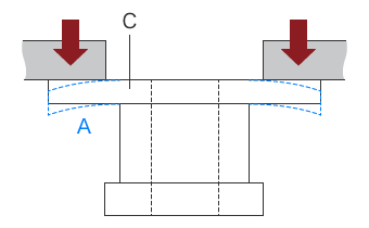
- A
- Deformation
- B
- Support jig
- C
- Workpiece
- Clamping force
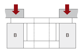
- • Machining pressure
-
- A
- Cutting tool
- B
- Deformation caused by machining pressure
A workpiece can become deformed by machining pressure when the workpiece is machined by a cutting tool. Effective countermeasures to prevent deformation include changing the workpiece shape by increasing the thickness at the deforming sections, reducing the amount of cutting, or lowering the hardness of the material. If the workpiece shape cannot be changed due to specifications or functional reasons, deformation can be prevented using a method called warpage removal. This is when a workpiece is roughly machined with extra thickness and is later finished by a separate machining process.
Deformation caused by cutting heat (working heat) and countermeasures to it
Cutting heat is generated by friction between the cutting tool and workpiece during cutting; it is said to reach 600 to 1000°C (1112 to 1832°F). Cutting heat is particularly higher when the workpiece is made of materials that have low thermal conductivity, such as stainless steel, because the heat generated by the cutting tool and workpiece cannot escape. Cutting heat causes the workpiece to expand. When the workpiece expands, the cutting depth becomes larger than the set depth; this results in a failure to produce the design dimensions. Effective countermeasures to prevent deformation include changing the cutting oil, using a combination of machining methods that produces less workpiece deformation (such as electrical discharge machining), or changing the workpiece materials.
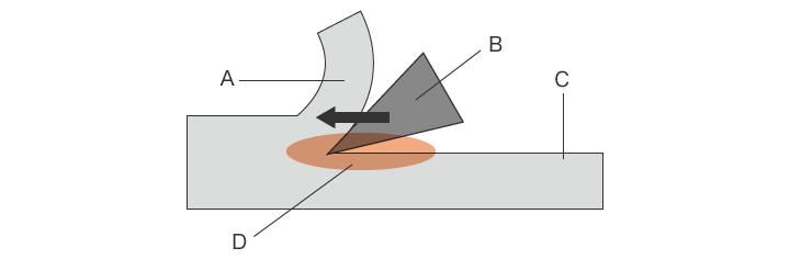
- A
- Chip
- B
- Cutting tool
- C
- Machined surface
- D
- Area where heat is generated
Deformation caused by residual stress and countermeasures to it
Stress remaining inside the workpiece even after the removal of clamping force, machining force, and all other external forces is called residual stress. The force acting inside an object from the inside toward the outside is supposed to be balanced with the force acting from the outside toward the inside. However, when this balance is disrupted by machining pressure and cutting heat during machining, warpage and strain can occur. Thin materials are particularly susceptible to warpage, and hard materials are particularly susceptible to warpage and strain. Even when the shape of a workpiece is normal while it is being clamped, it may deform after it is released from the clamp. To prevent this, the process known as annealing is performed. A workpiece is annealed before cutting to soften the workpiece making it easier to machine. It also equalizes hardness to prevent uneven machining and minimizes variation in workpiece hardness.
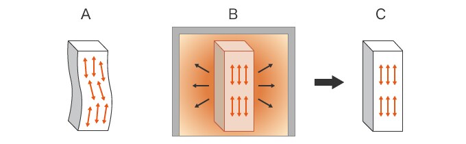
- A: Before annealing, a workpiece can easily deform or crack due to residual stress.
- B: During annealing, the workpiece is heated in an annealing furnace to release and remove residual stress through molecular motion.
- C: After annealing, the removal of residual stress prevents deformation after machining.
Problems in Conventional Measurement of Free-form Surfaces
It is extremely important that the dimensions and shapes of free-form surfaces, such as those of impeller blades and spiral gear teeth, are as intended. Highly accurate and quantitative 3D shape measurement is required for cross-sectional shapes as they can greatly affect strength and operation accuracy.
Typically, coordinate measuring machines or calipers are used for measurement; however, these methods involve a number of problems such as difficulty in achieving accurate measurement and variation in measurement from user to user. These include the difficulty in achieving accurate measurement with a coordinate measuring machine, and variation in measurement depending on the operator when using calipers. In addition, much time is required to identify the cause and solution when a problem occurs during machining.
Problems in measurement using a coordinate measuring machine
A coordinate measuring machine is typically used when measuring a free-form surface by using a probe to contact particular points on the target measurement surface. The probe needs to accurately contact the predetermined points.
When the measurement area is large, accuracy can be increased by increasing the number of measured points to collect more measurement data.
However, using this method for measurement of free-form surfaces involves the following problems.
- A large number of points need to be collected in order to measure the thickness of an impeller blade or the shape of a gear tooth surface. This requires time, and even when it is done, it is still impossible to identify the entire detailed shape.
- Comparison with CAD data takes time and effort due to difficulties in matching the positions in the measured data with the CAD data; it also requires a lot of work to input design values and tolerances.
- Because profiles and other shapes are measured by profile measurement, it is difficult to gain a picture of the entire surface.
Problems in measurement using tooth thickness calipers or a tooth thickness micrometer
When gear tooth thickness is measured using a handheld tool such as tooth thickness calipers or a tooth thickness micrometer, the over-pin measurement method is used.
With handheld tools, measurement conditions such as the contact force (measuring force), differ depending on the operator as each point needs to be selected and measured by hand. This results in variation in the measurement values and makes it difficult to obtain quantitative measurements.
Users also have to cut their sample in order to perform cross-sectional measurement, and it impossible to identify cross-sectional shapes through point measurement.
Solution to Problems in Measurement of Free-form Surfaces
In all, the problems with conventional measurement tools is that they cannot capture full surface 3D data due to the fact that area measurement is done by means of point and line contact.
To resolve these measurement problems, KEYENCE has developed the VL Series 3D Scanner CMM. The VL Series accurately captures the 3D shape of the entire target surface without contacting the target. A 3D scan of the target on the stage can be completed in as little as one second, for high accuracy measurement of the 3D shape. This allows quantitative measurement to be performed easily without variation in the measurement results. Some specific examples of the advantages of the VL Series are explained below.
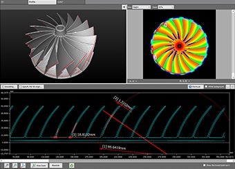
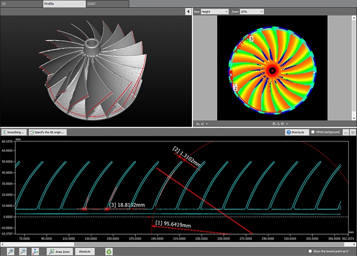
Advantage 1: Visualize differences from the 3D-CAD data in color.
It is possible to compare a product’s 3D-CAD data with the acquired measurement data for color visualization of any differences between the actual product and the design. This can dramatically reduce the number of man-hours required to analyze the shape of products.
The 3D data can be rotated in any direction, enabling specified locations to be measured, such as the pitch and curved shapes of impeller blades. Additionally, longitudinal and transverse cross-sections can be measured without destroying the workpiece.
The entire shape can be identified and the dimensions of specific locations can be measured by simple click operations, enabling quantitative measurement that is not affected by the skill level of the operator.
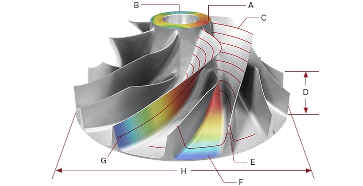
Measuring specific locations by the selected method
- A
- Maximum point of flatness/GD&T
- B
- Minimum point of flatness/GD&T
- C
- Profile measurement
- D
- Height measurement
- E
- Angle measurement
- F
- Differences from CAD data
- G
- Radius measurement
- H
- Width measurement

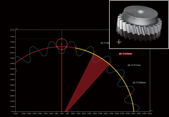
Advantage 2: Easy measurement of over-pin dimensions. Cross-sections can be clearly identified without the need to cut the target.
Over-pin dimensions of a gear measured using tooth thickness calipers or a tooth thickness micrometer lack reliability and stability. This is because the measurement points vary depending on the operator. Along with that, the jaw and spindle may be unable to actually reach the measurement points. Because measurement is based only on individual points, it is difficult to measure 3D shapes.
With the VL Series, you only need to place the target on the stage and scan it. The 3D shape of the target can be captured by non-contact means and no positioning is required. It is possible to display the entire target or to measure the profile at any location. This makes it possible to visualize and identify the locations and precise numerical values of shape defects.
The VL Series can also measure cross-sections when comparing the acquired data with 3D-CAD data without the need to cut the workpiece. Over-pin dimensions and tooth shapes can be visualized in color using the acquired 3D data. This enables cross-sectional measurement to be performed easily, without contacting the target. By checking for misalignment of cut profiles, it is possible to rapidly detect and enact countermeasures to machining deformation and other defects.
Summary
The VL Series can instantaneously and accurately measure free-form surfaces by high-speed 3D scanning without contacting the cutting product.
- No positioning is required. Measurement can be performed simply by placing the target on the stage and clicking a button, eliminating variation in measured values among different operators.
- Because the entire surface is measured, it is possible to identify all defect locations on the target allowing users to take profile measurements anywhere on their part. The VL Series enables the analysis of parts which could not be measured before, such as analysis of the thickness and pitch of spiral gear teeth and impeller blades.
- Cross-sections can be measured at the specified angles. Circular elements contacting grooves can be created by specifying the diameter. Longitudinal and transverse cross sections can also be measured at any location without destroying the workpiece.
- The 3D shape can be displayed in a color map. By sharing data that is visually easy to understand, it is possible to identify OK/NG products and to smoothly formulate and implement countermeasures to deformation caused by machining.
In this way, the VL Series can deliver dramatic improvements in efficiency for work such as measurement of machined products having free-form surfaces, defect analysis, and defect countermeasures that are indispensable to quality control in machining processes.
