
A Method for Accurately and Easily Measuring Fillets and Rounds
Fillets and rounds can be seen on corners of various parts and products. So why are these corners rounded? Also, how are they machined? Rounding off an interior corner creates a fillet, while rounding off an exterior corner creates a round. Fillets and rounds are three dimensional shapes, which makes them difficult to measure.
This page explains how fillets and rounds are machined, their notation in drawings, and their relationship with strength. It also introduces problems in measurement and a solution to these problems.
- Fillets and Rounds
- How Fillets and Rounds Are Machined and Their Notation in Drawings
- Relationship between Fillets and Strength
- Measurement Difficulties
- Fillets and Rounds Measurement Solutions
- Summary: Measure Fillets and Rounds with Greater Efficiency
Fillets and Rounds
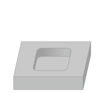
Fillets and rounds are corners that have rounded shapes. The corners of boards and square timbers are rounded off mainly for improving strength and safety. Surfaces may have fillets or rounds so as to improve usability, touch feel, and design. These surfaces are called rounded surfaces.
How Fillets and Rounds Are Machined and Their Notation in Drawings
Sheared or punched edges are sharp due to burrs and other factors, and they need to be handled carefully. A process to remove sharp pieces from these edges is called deburring, and a process to round these edges while deburring is called rounding. Fillets and rounds are described with a letter R on drawings, indicating the radius to be cut.
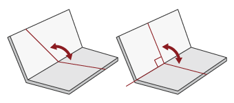
Corner rounding (fillets)
The main tools used to round corners are end mills and edge cutters. In manual machining, tools such as files and abrasive belts are used. Small fillets or rounds having a radius of less than 1 mm (0.03”) may be machined by grinding, electrical discharge machining, or wire cutting. Unlike chamfering that cuts off a corner at an angle, fillets and rounds need to be cut in an arc. This requires special tools and programming when numerical control machining is used.
- Example of fillet machining using an end mill
-
-
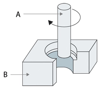
- A
- End mill
- B
- Part
-
-
Notation of fillets and rounds in drawings
Fillets and rounds are indicated in drawings by a combination of the letter R and a number, for example R5 or R10. This R usually indicates the radius of rounded edges. The number next to the R is the radius of rounding in units of mm. In other words, it indicates the radius (length) of the arc when creating a round by cutting the corner. The following figure shows an example of the drawing notation “R3” and the corresponding machining contents.
When a part has more than one fillet or round, this is often indicated as “number of corners-R3.” A rectangle having three rounded corners is indicated as “3-R3.”
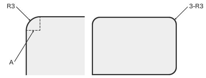
- A
- Radius of 3 mm (0.11”)
Relationship between Fillets and Strength
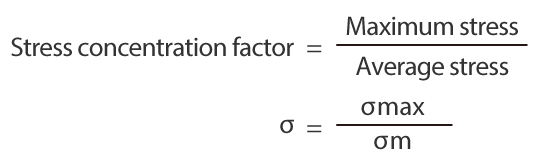
Strength can be improved by making an appropriate fillet at the base of an L- or T-shaped part. For example, the strength of the following cantilever can be improved by making a fillet at a base. Without a fillet at the base, loads will be concentrated in the corner. The phenomenon in which loads become concentrated in the base of this cantilever is called stress concentration, and the degree of concentration is called the stress concentration factor. The radius of the base corner has the following relationship with the stress concentration factor.
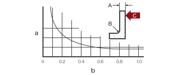
- A
- Thickness
- B
- Radius at the base
- C
- Load
- a
- Stress concentration factor
- b
- Ratio of thickness to radius
As shown above, the fillet at the base of the cantilever disperses loads and increases strength.
Measurement Difficulties
It is extremely important to verify that corners have been machined to the desired dimensions (within tolerances) and shapes. Fillets and rounds are three dimensional shapes, and require quantitative 3D shape measurement with high accuracy.
However, there are various problems in measurement using conventional measuring instruments, such as coordinate measuring machines, profile measurement systems, radius gauges, CR calipers, CR measuring gauges, and radius measuring instruments. For example, a high level of difficulty is involved in order to accurately measure the 3D shapes, resulting in variation in the measured values.
Measurement Difficulties - CMM
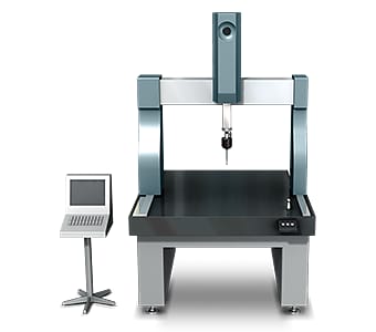
Typical coordinate measuring machines measure shapes by “scanning” a contact probe to across the surface to trace and measure the shape. During scanning, multiple points are measured at a specified pitch.
This method typically experiences the following problems:
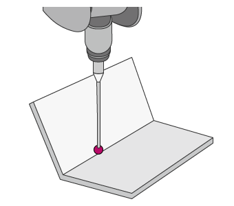
- It is extremely difficult to trace the probe or stylus along the desired line, such as a straight line at the center of a cylinder, a straight line on a bend, or a line passing through the center of a circle. If a fillet or round has a wide center angle, then because the entire circle is calculated based on a short arc, even a small error in measurement will become largely magnified. Such differences in the measurement location can produce variation in the measured values.
- Even a small stylus has a diameter of around 2 mm (0.07”). When measuring a 3D shape with a small radius, the stylus may be unable to contact the measurement point. In addition, because measurement accuracy is proportional to the number of measurement points or lines, many points or lines need to be measured.
In this way, measurement using a coordinate measuring machine involves significant problems, including the fact that not all workplace operators can accurately measure shapes, the existence of parts that cannot be measured at all, and limited locations where the machine can be installed.
Measurement difficulties - Profilometer
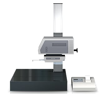
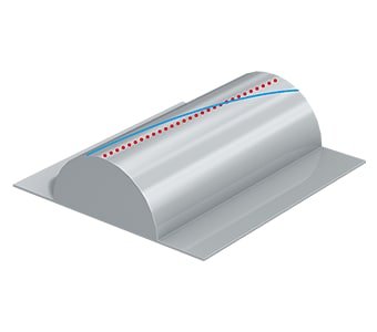
A profile measurement system must trace an accurate measurement line perpendicular to the fillet or round corner shape.
Profilometers experience the following problems:
- Measurement is time consuming, including the time require to fixture the target and level it.
- The stylus of a profile measurement system moves up and down in an arc centered on the fulcrum of the stylus arm, and the tip of the stylus also moves in the X-axis direction. This produces error in the X-axis data.
- Tracing the desired line with the stylus is extremely difficult work, and even slight displacement of the stylus produces error in the measured values.
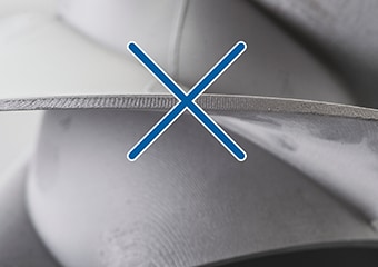
Measurement difficulties - Hand tools
measured using calipers.
Handheld tools, such as radius gauges and CR calipers are very convenient for measurement. However, there are multiple causes which result in measurement error or variation in the measurement data.
With calipers or a gauge, measurement conditions such as the contact force (measuring force) when measuring each point by hand and selection of the measured points differ depending on the operator. This results in variation in the measurement values and makes it difficult to obtain quantitative measurements. Shapes such as thin fins and blades also cannot be measured.
Fillets and Rounds Measurement Solutions
Reviewing the problems of conventional measuring instruments shows that there is a certain point which the problems all have in common. This is that measurement of a three-dimensional target or area is done by means of point and line contact.
To resolve these measurement problems, KEYENCE has developed the 3D Optical Profilometer VR Series. The VR Series accurately captures the 3D shape of the entire target surface without contacting the target. A 3D scan of the target on the stage can be completed in as little as one second, for high accuracy measurement of the 3D shape. The VR Series is capable of instantaneous and quantitative measurement with no errors in the measurement results. Some specific examples of the advantages are explained below.
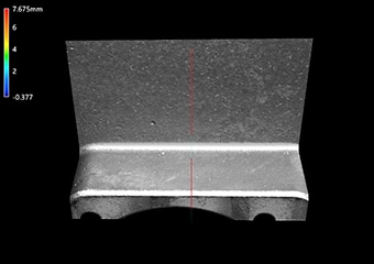
Advantage 1: Capable of measuring recessed areas
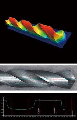
The VR Series can measure areas where a probe or stylus cannot reach. With a contact-type measuring instrument, it is difficult to measure targets where the pitch is small and there are recesses, such as blade tools and heatsink fins. The VR Series can also measure cross-section shapes at the same time.
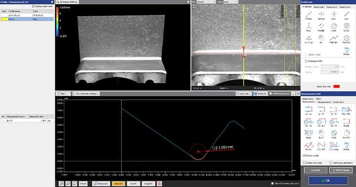
The VR Series can measure fillets, rounds, and their heights by virtually cutting the workpiece. Workpiece shapes can be analyzed in a short time by using the analysis templates which allow users to register the measurement items in advance. This makes it possible to rapidly perform measurement which previously required much time or was not possible.

Advantage 2: No fixturing required.
Measurement can be performed simply by placing the target on the stage and pressing a button.
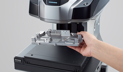
Unlike conventional measuring instruments, the VR Series extracts the features of the target placed on the stage, and automatically corrects its position. The strict positioning which previously required much time and effort is no longer necessary. This makes it possible for even an inexperienced operator to easily and instantaneously perform measurement, and eliminates the need to assign a specialized operator to measurement work.
Advantage 3: No measurement variation
The VR Series can automatically draw profile lines perpendicular to the fillet or round. This eliminates variation in the measurement results and ensures different operators will obtain the same measurement results.


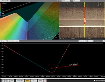
Once a workpiece has been scanned, its profile (cross-section) can also be measured at locations different from the locations used in past measurement. This eliminates the need to set and measure the same target again. This also enables comparisons with past data to check the differences in shape when a workpiece is supposed to have the same shape but was manufactured in a different lot using different materials under different processing conditions.
Summary: Measure Fillets and Rounds with Greater Efficiency
The VR Series resolves the problems faced by conventional measuring instruments by instantaneously measuring accurate 3D target shapes with high-speed, non-contact 3D scanning.
- No measurement variation across different operators.
- Without the need for positioning or other preparation, measurement can be done simply by placing the target on the stage and pressing a button. This eliminates the need to assign a specialized operator for measurement work.
- 3D shapes can be measured easily at high speeds with high accuracy. This makes it possible to measure a large number of targets in a short time, helping to improve quality.
This system also allows comparisons with past 3D shape data and CAD data, as well as easy data analysis such as distribution within tolerances. It can be used effectively for a wide range of purposes including product development, manufacturing trend analysis, and sampling inspections.
