
Accurately Measure Cast Products
Casting is suitable for producing complex-shaped products and large products, although the strength is inferior to products manufactured by rolling or forging. Casting also has the advantage of enabling mass-production at lower costs. Making use of these advantages, casting is used to manufacture parts in a wide range of fields including automobiles and other transportation machinery, industrial machinery, electrical equipment, communication equipment, and daily necessities.
However, internal and external defects form easily in cast products due to causes such as metal viscosity, temperature, or contamination during casting.
This section explains the most common casting methods, types of problems, prototype measurement in development and design, and a measurement method that can prevent outflow of defects in mass production. It also introduces problems in conventional measurement methods and a solution to them.
- Casting
- Types of Casting
- Defects Occurring in Cast Products
- Measurement Difficulties
- Cast Product Measurement Solutions
- Summary: Higher Efficiency in the Measurement of Cast Products
Casting
Casting is a metal working process in which molten metal is poured into a cavity of the desired shape, where it then cools and solidifies. Such a cavity with the desired shape is called a mold, and a product manufactured by casting is called a casting or cast product. Molds include metal molds created by shaving metal, as well as other molds made of sand, resin, or gypsum. Metal molds and sand molds are the types most commonly used. The metals used in casting include cast iron, cast steel, aluminum alloys, and magnesium alloys, and are selected according to the needs of the end product.
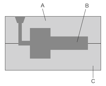
- A
- Mold (upper mold)
- B
- Cast product
- C
- Mold (lower mold)
Types of Casting
Casting can be categorized based on various items such as the casting mold material, mold production method, and model type. This section focuses on categories based on the casting mold material, which is the most common means of categorization. It explains the sand casting, permanent mold casting, and lost-wax casting types.
Sand casting
Sand casting is a method in which molten metal is poured into a sand mold with the desired shape, where it then cools and solidifies. The sand which is used to form the mold is called molding sand, and it is composed of silica sand grains mixed with a binder or additive such as bentonite (clay mineral), waterglass, or resin. Molds made of sand are called sand molds.
Sand molds support complex shapes and when they are used for in small-lot manufacturing, they can be created at lower costs and more quickly than molds used in permanent mold casting. However, due to the lower cooling speeds during casting, cast products produced by sand casting generally have lower dimensional accuracy and lower strength compared to products produced by other methods. Additionally, a sand mold is destroyed after a single use, which results in higher running costs for mass production.
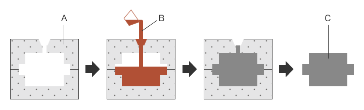
- A
- Sand mold
- B
- Molten metal
- C
- Cast product
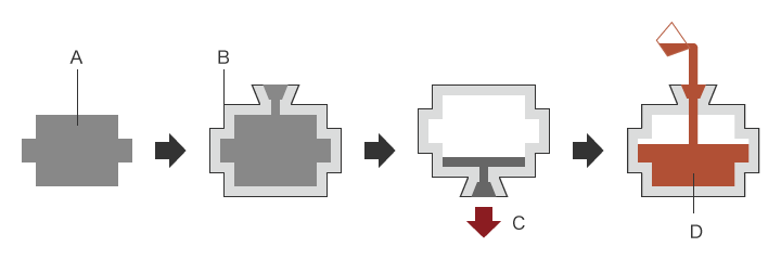
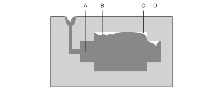
Permanent mold casting
Permanent mold casting is a casting method in which molten metal is poured into a metal mold, where it then cools and solidifies.
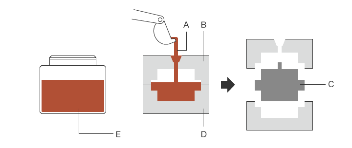
- A
- Molten metal
- B
- Mold (upper mold)
- C
- Cast product
- D
- Mold (lower mold)
- E
- Molten metal
- Gravity casting:
- Gravity casting uses gravity to fill the mold with molten metal. Gravity is also used in sand casting, but the molds used in this method can be used repeatedly, making them more suitable for mass production. Because the molten metal cools rapidly, gravity casting can produce cast products with superior mechanical properties. The molten metal is also poured at low speeds, resulting in less inclusion of air and gases than in die casting. Because pressure is not applied when the mold is filled, it is possible to use parts called cores to produce cast products with complex shapes and hollow interiors.
Due to these advantages, gravity casting is the most common method used to produce a wide range of cast products. However, this method also has some disadvantages. For example, because no pressure is applied, the mold must be completely filled with molten metal, reducing the yield rate. The low filling speed also increases the cycle time. - High pressure casting:
- In high pressure casting, the mold is filled with molten metal at low speed, and pressure is applied from the outside as the metal solidifies. Because the mold is filled with molten metal at low speed, this results in less inclusion of air and gases than in die casting. Because the pressure is higher than gravity casting, this method can produce mechanically strong cast products with fine metal structures.
Pressure can be applied directly or indirectly. With direct pressure application, a pressure plunger called a punch is used to directly apply pressure to the molten metal. With indirect pressure application, pressure is applied as the mold cavity is filled with molten metal by means of a plunger. Generally speaking, direct pressure application is considered more suitable for producing cast products with simple shapes, while indirect pressure application is considered more suitable for producing medium- or large-sized cast products having complex shapes. - Low pressure casting:
- With low pressure casting, the mold is filled with molten metal by means of compressed air or inert gas pressure. The molten metal reaches every corner of the mold cavity, and remains pressurized until it cools and solidifies. This reduces the occurrence of defects such as shrinkage cavities and blowholes. Pressure application is stopped when the molten metal at the gate has solidified, and molten metal not needed to produce the cast product returns to the crucible. This results in yield rates that are higher than those of sand casting and gravity casting. Cores can also be used in the same way as gravity casting, making it possible to produce cast products with complex shapes and hollow interiors. At the same time, the long cooling time with this method results in the disadvantage of lower productivity due to the long cycle time.
- Centrifugal casting:
- With centrifugal casting, molten metal is poured into a cylindrical mold that is rotating at high speed. Centrifugal force causes the molten metal to spread out along the inside of wall of the mold, forming it into a cylindrical cast product. The cylinders may be vertical or horizontal. Vertical molds are used to produce short cast products. Horizontal molds are used to produce long cast products. Centrifugal casting can produce hollow cast products without the use of cores. It has other advantages including no need for a gate or pressure application, and the metal density of the cast product can be changed by controlling the rotation speed. With a short cooling time, centrifugal casting is suitable for casting fast-solidifying materials and producing thin pipes. It can also produce cast products with complex shapes. As a result, centrifugal casting is used to produce cast products such as water pipes, gas pipes, bearing metal, and silver dental crowns. Centrifugal casting also has disadvantages such as the occurrence of segregation caused by the centrifugal force, as well as cracking that can occur immediately after cooling.
- Die casting:
- With die casting, molten metal is injected into a mold under high pressure at high speed, and is then cooled in a short time. Die casting enables casting of elaborate shapes with highly accurate dimensions, and the short cycle time makes it suitable for mass production. Die casting is mainly used for casting metals that have low melting points, such as aluminum alloys, zinc alloys, and magnesium alloys. There are two types of die casting machines: hot-chamber machines and cold-chamber machines.
In a hot-chamber machine, the casting machine is integrated with a furnace containing the molten metal. This type of machine is primarily used for magnesium alloy casting. In a cold-chamber machine, the casting machine and furnace containing the molten metal are separate. The molten metal is poured into the injection port using a ladle.
Cold-chamber machines are primarily used for magnesium alloy casting. Die casting enables casting of elaborate shapes with highly accurate dimensions, however a disadvantage is that the high-speed injection of molten metal into the die can cause air, mold release agent, and other substances to enter the cast product. For this reason, cast products produced by die casting cannot be used as parts that require strength.
Lost-wax casting
Lost-wax casting, also known as investment casting, is a precision casting method. A model is created using a mixture of materials having low melting points, such as paraffin, resin, and filler. The model is then covered with a refractory material such as ceramic. The model is then melted and flows out to create the mold. One advantage of lost-wax casting is that because the molds do not need to open, it can cast metal in complex shapes that are impossible with sand casting or other permanent mold casting. In addition, because the molds are made of a refractory material such as ceramic, this method can be used to cast metal with high melting points such as carbon steel and stainless steel. A disadvantage of lost-wax casting is that the molds must be discarded after one use, which makes this method unsuitable for mass production.
- A
- Model
- B
- Refractory material (mold)
- C
- Wax removal
- D
- Molten metal
Defects Occurring in Cast Products
During casting, defects can occur as a result of various causes. It is necessary to immediately identify the cause and enact countermeasures because defects can reduce the yield rate, and can also cause the return or recall of products. This section introduces some typical types of defects that occur during casting.
Shrinkage cavity
The molten metal which fills the mold shrinks as it cools. When the cooled metal starts to solidify, it shrinks further. The amount of shrinkage must be replenished with molten metal from a part that has not yet solidified. However because molten metal cannot be added after the product has solidified, voids or indentations form at locations where the amount of molten metal was insufficient. These voids and indentations are called shrinkage cavities.
Shrinkage cavities occur on the inside and outside of cast products. External shrinkage cavities are also called open shrinkage cavities, and are indentations occurring on part of a cast product surface. Internal shrinkage cavities are voids that form inside a cast product. The surface of the cavity is rough and is bluish-purple or blackish-brown in color. Both types of shrinkage cavities occur at the parts which solidify last, such as thick parts, intersecting parts, corners, edges, and gates.
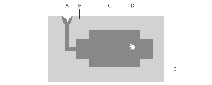
- A
- External shrinkage cavity
- B
- Mold (upper mold)
- C
- Cast product
- D
- Internal shrinkage cavity
- E
- Mold (lower mold)
Blowhole, pinhole
Blowholes and pinholes are defects which form round voids inside of a cast product. These defects occur when a gas or air enters the molten metal that is fed into the mold. The name is determined by the void size. A void with a diameter of 2 mm (0.08”) or more is called a blowhole, while a void with a diameter of less than 2 mm (0.08”) is called a pinhole.
The gases which cause these defects are generated by chemical reactions between the molten metal and foreign substances, or by moisture. In die casting and other casting that injects molten metal at high speeds, blowholes and pinholes can occur when air becomes trapped in the molten metal.
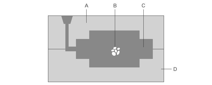
- A
- Mold (upper mold)
- B
- Blow holes/pinholes
- C
- Cast product
- D
- Mold (lower mold)
Cracking
Cracking is a defect in which cracks appear in the cast product. Cracking that occurs at high temperatures is different from cracking that occurs at low temperatures. Cracking that occurs at high temperatures is called hot cracking, with cracking occurring in the part which solidifies last. Cracking that occurs at low temperatures is called cold cracking, with cracking occurring during or after cooling. Cracking occurring when a solidified part pulls on an unsolidified part during the solidification process is called shrinkage cracking or solidification cracking. Cracking which occurs due to mechanical stress caused by uneven thickness or stress caused by shrinkage is called strain cracking.
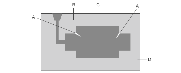
- A
- Cracking
- B
- Mold (upper mold)
- C
- Cast product
- D
- Mold (lower mold)
Misrun
A misrun is a defect in which the mold cavity fails to be filled all the way with molten metal, resulting in an incomplete cast product shape. Misrun occurs at thin or narrow parts, creating a shape with rounded edges. This defect occurs when molten metal fails to completely fill the mold cavity, and may be caused by mold cavities that are too narrow, low speed of molten metal filling, low mold temperature, or insufficient degassing of the mold cavity. Other defects that can occur as a result of inappropriate molten metal filling include cold shuts, which form a boundary line on the cast product surface, and flow lines, which form irregular wrinkles on the cast product surface.
- A
- Cast product
- B
- Flow line
- C
- Misrun
- D
- Cold shut
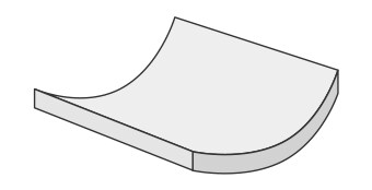
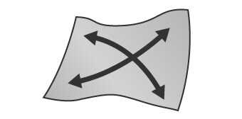
Strain (warpage, waviness)
Strain which occurs in cast products includes warpage and waviness, and is caused by a problem in the casting process. In casting that forms a shape with metal melted at high temperature, the cooling speed varies with different thicknesses and at different locations. Thin parts cool faster, while thick parts and the parts which were filled last take more time to cool. When an inside part that takes time to cool pulls on a part that has already cooled, this generates residual stress, which is a cause of strain.
Measurement Difficulties
It is extremely important to confirm that the dimensions and shape of a cast product are as intended (within the tolerances). Highly accurate and quantitative 3D shape measurement is required, especially for cast products that are used as precision parts or cast products with complex shapes because these cast products can affect strength and performance.
Some conventional measuring instruments, such as coordinate measuring machines and simplified 3D scanners, cannot measure certain locations on a product, and can have low measurement accuracy. Many causes of defects cannot be identified by analysis which is based on measurement data acquired using these measuring instruments. Additionally, measurement using these instruments requires a lot of time.
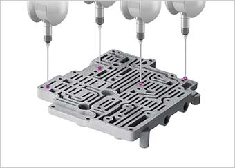
Measurement difficulties - CMM
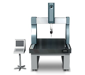
For example, when measuring casting defects such as shrinkage cavities, cracking, and misruns in a small area using a coordinate measuring machine, a virtual surface of that area must be created using a probe. However it is extremely difficult to perform accurate measurement using this method. It is also difficult to identify the accurate 3D shape when a measuring a small area because of the small number of measurement points.
Measurement difficulties - 3D Scanner
With a 3D scanner, shape measurement is relatively easy because the instrument directs light onto the workpiece and measures its shape using the light reflected back from the workpiece. However, conventional 3D scanners can suffer from low image resolution, long processing speeds, and low accuracy when measuring complex surfaces. 3D scanners may also be unable to measure shapes correctly depending on the workpiece position and posture, and the lack of measurement functions makes it impossible to conduct adequate inspections.
Cast Product Measurement Solutions
Shape analysis is indispensable in order to guarantee the quality of cast products. However, CMMs require the operator to have a high skill level, and capturing data can be time consuming. In addition, many simplified 3D scanners are not equipped with the systems and accuracy that are required for use during the research and development stage, testing to determine welding conditions, defect cause analysis, and rapid troubleshooting.
To resolve these measurement problems, KEYENCE has developed the 3D Scanner CMM VL Series.
The VL Series accurately captures the 3D shape of the entire target surface without contacting the target. A 3D scan of the target on the stage can be completed in as little as one second, for high accuracy measurement of the 3D shape. It is capable of instantaneous and quantitative measurement with no variation in measurement results even when operated by new users. This section introduces some specific advantages of the VL Series.
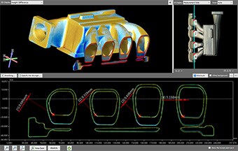
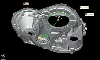
Advantage 1: The 3D shape of the entire target surface can be captured with a single measurement.
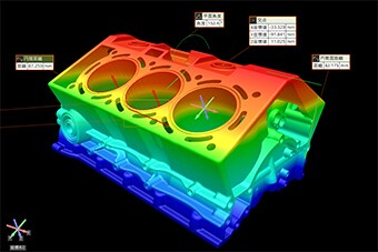
With a single click, the VL Series can acquire 16 million data points, enabling accurate measurement of complex cast products.
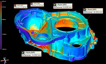
The maximum and minimum surface irregularities can be displayed in an easy-to-understand manner in a color map, making it possible to identify the locations of defects. Cross-sections can also be measured during 3D comparison.
Furthermore, measurement data from multiple targets can be compared side by side, and the desired conditions can be applied to multiple data sets at once.
These functions can dramatically reduce the number of man-hours required to analyze the shapes of products.

Advantage 2: Operation is easy and measurement can be performed by anyone without variation in the measured values.
3D shape measurement can be performed easily just by placing the target on the stage and clicking a button. Because automatic position adjustment is possible based on target feature data, strict leveling or positioning is not required. This series includes the Smart Stage function that automatically configures the measurement range according to the target size. This eliminates the work that was required to set the measurement length and Z-range.
A total of eleven GD&T measurement tools are available for measuring form tolerances, orientation tolerances, and position tolerances using the acquired 3D data. While flatness measurement ordinarily requires much time because of the need to measure many individual points, the VL Series can complete measurement in an instant by optically capturing the surface. High precision analysis can be performed for the entire shapes or any part of it, enabling prompt and accurate troubleshooting.
In addition to simple setup, the easy operation of the VL Series makes it possible for operators who are unfamiliar with measurement to measure shapes accurately. As a result, the number of samples can easily be increased not only for R&D and testing to decide conditions, but also for measurement and inspection of products during commercial production.
![[Shape tolerance] Flatness, Cylindricity, Straightness, Circularity [Orientation tolerance] Parallelism, Perpendicularity, Angularity [Position tolerance] Position, Concentricity, Coaxiality, Symmetry](https://www.keyence.com/Images/ss_measurement-solutions_casting_017_2012816.png)
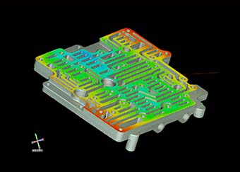
Advantage 3: Differences from 3D-CAD data can be visualized in color.
It is possible to compare a product’s 3D-CAD data with the acquired measurement data to visualize any differences between the actual product and the design. For objects that were difficult to measure by conventional means, comparing the measurement results with the 3D-CAD data allows previously undetected defects to be identified. This makes it possible for the development and design staff to provide immediate feedback. This dramatically reduces the time required for analysis when investigating casting defects, identifying the cause, and other related activities.
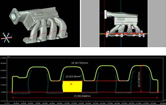
Because a wide range of dimensional measurements are supported, precisely measuring the dimensions at locations of concern allows problems to be analyzed in detail.
measurements with extensive tools
displayed in a color map
Summary: Higher Efficiency in the Measurement of Cast Products
The VL Series can accurately and instantaneously measure the 3D shapes of cast products by high-speed 3D scanning without contacting the target, offering the following advantages:
- Because the entire surface is measured, it is possible to identify all defect locations on the target, and to perform profile measurement at any desired part.
- Non-contact, high-accuracy shape measurement is possible even for targets that have complex shapes.
- No positioning is required. Measurement can be performed simply by placing the target on the stage and clicking a button.
- The 3D shapes can be displayed in a color map. Being able to share data that is visually easy to understand makes it possible to smoothly implement countermeasures to casting defects.
- Multiple sets of measurement data can be easily and quantitatively compared and analyzed.
- OK/NG product judgments are possible. Data can be shared for rapid analysis of NG products.
The VL Series delivers dramatic improvements in efficiency for measurement, defect analysis, and the implementation of countermeasures.
