
What Are Pulse Signals?
This section provides an overview of pulse signals, which are used for various types of measurement and detection.
“Waves” of electrical signals—pulse signals
The “frequency” is the number of electrical signal vibrations that are repeated per unit of time, and “Hz (hertz)” is a unit that indicates the number of vibrations per second. The (square) waves of electrical signals that occur in such a short period of time and have a certain width are called “pulses” or “pulse signals.”

Classification of pulse signals
There are various types of pulse signals, and they are classified according to their characteristics. Major ways to classify pulses are introduced below.
1. Classification by count
Single pulses refer to pulses that are generated only once when an event occurs, whereas successive pulses refer to pulses that are repeatedly generated in succession. Applications of single pulses include passage detection, while those of successive pulses include motor speed measurement.

- A
- Successive pulses
- B
- Single pulse
2. Classification by duration (width)
The time interval from the half point between the rising edge of a pulse and the peak to the half point between the peak and the falling edge is called the pulse duration. There are a wide variety of pulses—from those having an extremely short pulse duration like 0.1 μs to those having a duration of several seconds.
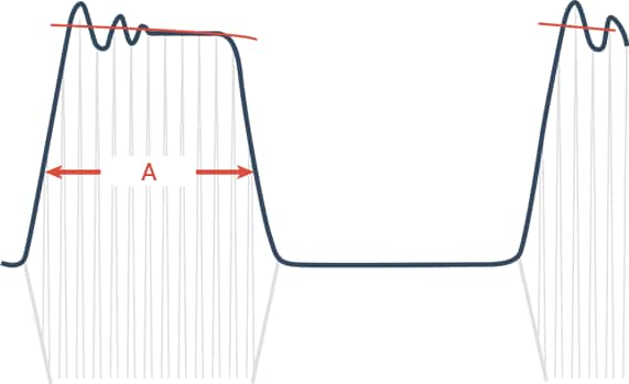
- A
- Pulse duration
3. Classification by interval
This classification is based on the time interval between when repeated pulses are turned on and off. While the pulse duration refers to the period when pulses are turned on, this classification indicates the period when pulses are turned off. To increase the bit rate for optical communication or the like, it is necessary to put as many pulses as possible within a unit of time. In turn, this condition requires that the interval between output pulse signals be reduced.
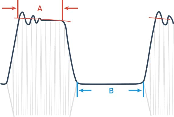
- A
- Pulses on
- B
- Pulses off
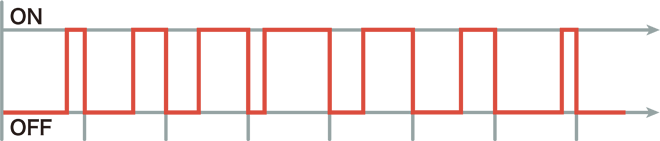
4. Classification by regularity
Pulses are classified according to whether they occur with a certain regularity or completely irregularly. Typical regular pulses include “serial communication signals,” whereas “human detection” is a typical example of irregular pulses.
Applications and modulation methods of pulses
Applications of pulses are largely classified into “measurement using input signals” and “control of something by outputting signals.” Basic measurement applications include detection of motor speed through the use of a rotary encoder or a similar device to display and analyze the speed on the basis of pulse signals. On the other hand, typical systems that control driving using pulses include various types of motors such as stepping motors (pulse motors) and servo motors.
Pulse modulation that controls motors
To control these systems, it is indispensable to “modulate” electrical signals, in other words, to “convert signals according to the characteristics of the transmission medium” in terms of information transmission. In particular, the method in which electrical signals are transmitted and generated according to pulse changes is called “pulse modulation.” The modulation methods used, especially common for motor control, are “pulse width modulation (PWM)” and “pulse amplitude modulation (PAM)”.
Pulse width modulation (PWM)
This method controls the current and voltage to pass depending on the pulse width (duration of continuous transmission) and the interval (time between pulses). The rate of “the period when pulses are on” in a certain period is called the “duty ratio (duty cycle),” and the optimal voltage is obtained by changing this rate. One feature of this method is its high efficiency because the voltage proportional to the pulse on duration can be obtained by shortening the on/off cycle. Another feature of this method is its fine control.
Pulse amplitude modulation (PAM)
Contrary to the pulse width modulation method, this method controls the current and voltage to pass depending on the pulse strength (amplitude). A pulse amplitude modulation inverter used for air-conditioning and similar systems changes the pulse voltage amplitude by controlling the voltage of the rectifier.
Other pulse modulations
Pulse code modulation (PCM)
This pulse modulation method converts input analog signals to digital signals (pulse trains) by sampling analog signals at a certain cycle and converting them to binary numbers (quantization). This method, also called analog-digital conversion, is used to transmit analog signals, such as sound, as digital signals. Its applications include CDs (CD-DAs), PCM recorders, and Blu-rays (BDMVs).
Pulse density modulation (PDM)
This modulation generates waveforms on the basis of the pulse density within a time period divided into a specific width. This is one of the methods to convert analog signals such as sound and video to digital signals by replacing them with pulse trains. This method enables conversion with a higher sound quality than the PCM—a conventionally used method. This method is used for a new CD standard called “Super Audio CD (SACD).”
Pulse position modulation (PPM)
This pulse modulation method converts signals to temporal pulse phase differences (positions) having a certain width. This method features good resistance to noise because pulse information can be determined on the basis of the pulse position. This method controls the voltage by changing the ratio when pulses are on in each AC cycle and is used as the control pulses for “thyristor drive” applied to lighting adjustment, temperature adjustment for heat sources, etc.

