Measurement System Types and Characteristics
Coordinate Measuring Machines
- What is Coordinate Measuring Machine (CMM)?
- Coordinate Measuring Machine (CMM) Parts
- How to Use a Coordinate Measuring Machine (CMM)
- Coordinate Measuring Machine (CMM) Measurement
- Problems of Coordinate Measuring Machines (CMM)
- Why choose KEYENCE?
What is Coordinate Measuring Machine (CMM)?
Conventionally, measurements were taken visually using hand tools or an optical comparator. However, these tools require significant time and have limited accuracy.
On the other hand, a coordinate measuring machine (CMM) measures the height, width, and depth of the part using coordinate processing technology. In addition, such machines can automatically measure the target, record the measured data, and obtain GD&T measurements.
A coordinate measuring machine (CMM) is either a contact model that uses touch probes, a spherical object used to perform measurements, or a non-contact model, which uses other methods such as cameras and lasers. Some models designed for the automotive industry can even measure targets larger than 10m (30 ft) in size.
Coordinate Measuring Machine (CMM) Advantages
The advantage of the coordinate measuring machine (CMM) is that it can measure items that are difficult to measure with other measuring machines with high accuracy.
For example, it is difficult to measure the three-dimensional coordinates of a specific point (hole, etc.) from the virtual origin with a hand tool such as a caliper or micrometer. Also, measurement using virtual points and virtual lines and geometrical tolerances are difficult with other measuring machines, but can be measured with a 3D CMM machine.
Coordinate Measuring Machine (CMM) Parts
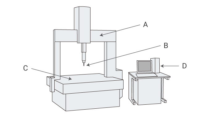
- A
- Moving bridge
- B
- Trigger probe
- C
- Stage
- D
- Controller
Typically, most CMMs are bridge or gantry-types as seen in the diagram. The spherical contact point attached to the tip of the probe is applied to the object on the stage, and the coordinate values in three dimensions (X, Y, Z) are specified and measured.
It is mainly used for three-dimensional measurement of dies such as automobile parts and various mechanical parts, three-dimensional objects such as prototypes, and measurement of differences from drawings.
Coordinate Measuring Machine (CMM) Accessories
Stylus / Probe Tip
Stylus of contact type CMM generally has a spherical diameter. Hard materials are often used at the probe tip - ruby and zirconia being the most common.
In addition to the spherical shape, a needle type with a sharp tip may be used.
Granite Table
In order to realize highly accurate measurement, the surface of a coordinate measuring machine is often a surface plate made of stone. The stone surface plate has a very small change in shape over time and is not easily scratched, so it has the advantage that it can be used stably for a long time.
Fixtures
One of the more critical tools for using a coordinate measuring machine are fixtures for fixing a measurement target in place.
The reason measurement target is fixtured it does not move during CMM operation because part movement will lead to errors. It is common to use tools such as a fixture plates, clamps, and magnets
Air Compressors & Dryers
Mechanically driven coordinate measuring machines require an air compressor with a dryer. This can be found is standard bridge or gantry-type CMMs.
Software
There are roughly two types of software for coordinate measuring machines.
The first is software for our own measuring machines that we independently developed for each measuring machine maker.
The second is software developed by a third-party that can be used by measuring instruments from multiple manufacturers.
How to Use a Coordinate Measuring Machine (CMM)
Place the measurement target in the metrology lab for at least 5 hours before measurement to allow the target to adjust to room temperature (generally 68°F). This will prevent measurement errors and discrepancies due to thermal expansion.
Perform measurements by directing the probe to your desired measurement location manually or with a control PC. The CMM will record the X,Y, Z coordinates of the probe location. As points are continued to be taken, the systems software will calculate specified dimensions such as diameters, lengths, angles and other critical dimensions.
Stylus Calibration (Probe Calibration)
Calibration on the stylus (probe tip) that comes into contact with the object must be performed in order to accurately begin measurement for two reasons. The first is to recognize the spherical center coordinates of the stylus. The second is to set the stylus sphere diameter. By setting the diameter, it is possible to calculate by offsetting the radius from the point actually touching (outside the sphere) to the sphere center coordinates.
For calibration, a sphere with a known sphericity, known as a reference sphere, is generally used.
Handling Precautions
Although some models can perform measurements on the order of 0.1 μm, correct usage and management are vital for measurement accuracy.
Verify that the moving parts move horizontally and vertically during use. Also, use a measurement standard or a similar object to check for indication errors.
In order to perform accurate measurements, allowing the temperature of the target to adjust to room temperature in the metrology lab is critical. Alternatively, the measurement parameters must be set to correct for any temperature difference.
For touch probes, it is important to ensure that the probe contacts the target at a constant speed during measurement.
Maintenance and Calibration
Regular CMMs require regular maintenance and inspection in order to carry out highly accurate measurements continuously. Especially in the case of a bridge-type CMM that are mechanically driven with sliding parts, it is necessary to regularly replace worn parts, lubricate, and clean the system for optimal performance.
Coordinate Measuring Machine (CMM) Operator Training
Careful handling of coordinate measuring machines generally requires advanced operator skills. Typically, CMM programmers are highly-trained metrology professionals.
CMM programmers are required not only for proper inspection, but a CMM may be damaged resulting in high repair costs if not used properly. For this reason, full-time inspectors are needed, and significant training is a pre-requisite for operation.
Coordinate Measuring Machine (CMM) Measurement
Coordinates and Alignment
CMMs generally have device coordinate system that is set in the object.
The device coordinate system is defined by the device, for example, the direction of the axis that moves in the lateral direction is the X axis, and the direction perpendicular to the stage surface is the Z axis. Therefore, depending on the orientation of the object to be measured, it may differ from the reference plane or reference line of the object itself. Since it is difficult and inaccurate to physically place this on the machine coordinates, the work coordinate system is set according to the reference plane or reference line of the object.
This way, aligning the orientation of the workpiece with the orientation of the reference coordinates is called alignment.
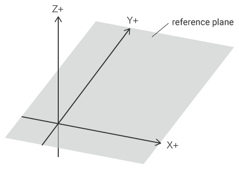
How to set coordinates
There are three pieces of information required to set the work coordinate system.
The first is the plane that is the reference plane, and the direction perpendicular to this plane is the Z axis.
The second line is the reference line, which is generally the X-axis and the vertical direction is the Y-axis. The straight line may be measured directly from the object, or it may be a straight line connecting two different points (such as two holes) with a virtual line.
The third point is the origin. This origin is the 0 point of each coordinate value of X, Y and Z. It is also possible to specify a specific point (for example, the center point of a specific hole) as the origin, or a virtual point (intersection point) where two straight lines intersect.
Measuring Dimensions and 3D features
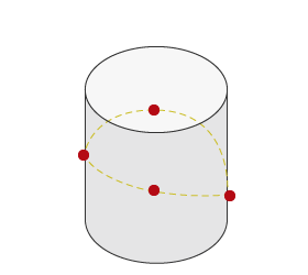
Generally, a user would select a measurement target called "element" such as a plane via a software menu and begin measurement. In the case of a contact type coordinate measuring machine, the stylus tip is brought into contact with the object to be measured, and the measurement point is taken. The element is measured by measuring the minimum number of measurement points specified for each element. If the number of measurement points is further increased, it is often calculated by the least squares method.
In addition to planes, measurement elements include lines, points, circles, cylinders, cones, and spheres.
Dimensions and 3D shapes are measured by calculating the distances and angles between measured elements.
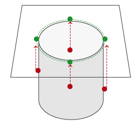
Virtual Figures (Projection)
Some elements have three-dimensional shapes such as cylinders and cones, but some elements do not have three-dimensional shapes such as lines and circles. These elements are generally projected on a plane (moved perpendicular to the plane direction) so that they can be measured correctly. The plane that is projected is called the reference plane or projection plane.
Measuring Virtual Figures
Coordinate measuring machines can also measure using virtual lines and points.
Various examples of virtual elements are used, such as intersections between straight lines, tolerances between planes, intersections between planes, and circles between cones and planes.
It can be said that measurement using these virtual elements, which is difficult to measure with hand tools such as calipers, is unique to 3D measurement.
Measuring GD&T
Geometric tolerance measurements are measured in the same way as regular measuring elements.
See the geometric tolerances page for more details.
Problems of Coordinate Measuring Machines (CMM)
Measurement Stability
To set and measure correctly, specialized knowledge and skills are required.
It is required to maintain an appropriate temperature in the measurement room and stabilize the temperature of the object.
Responsiveness
Since it is necessary to calibrate every time various settings and probe angles are changed, it is not easy to support frequent product changes.
Since a measurement room is required, it is difficult to perform frequent measurements while processing the object.
Cost and Effort
The installation requires a large space and the construction of an environmentally-controlled quality lab which is extremely expensive.
Maintenance costs for the measurement environment and measuring equipment can be a burden.
Significant time is required to program the CMM for a few reasons. The required time run the part to the quality lab, acquiring the appropriate temperature for the part, fixturing, calibration for each probe tip and the time needed to complete the measurement.
Why choose KEYENCE?
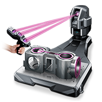
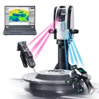
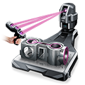
KEYENCE’s XM Series is a new type of coordinate measuring machine that overcomes conventional CMM obstacles. It’s a portable, benchtop CMM that allows any operator easily measure 3D/GD&T features. The unit also doesn’t require a controlled environment and can be used on the shop floor. Learn more about this next-generation CMM!